


1022410 – 0001 Rev. 2
Hardware installation 5–7
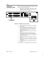
7.
Verify after approximately 30 seconds, that a
U
is displayed
on the UMOD light-emitting diode (LED). Also verify that
the cooling fan is operating. If a test fails, refer to
chapter 10, “Troubleshooting.”
8.
Set the O/| power switch to O. Verify that the front panel
LEDs are extinguished.
Refer to section 5.5, “Cable installation” on page 5–7 for
procedures that describe installing the IFL and user equipment
interface cables.
This section describes installing the IFL and user equipment
interface cables.
1.
This step describes installing the DTE device cables onto
the CIM. Refer to table 5-2 to locate the desired connection
type, then look for the checked (
√
) entries to determine
which CIM connectors will be used.
CIM Connectors
TO
DTE
G.703
BAL
ESC
SIGNALS RD SD
Connection Type
Balanced G.703
Balanced G.703, single-bearer D&I
Balanced G.703, twin-bearer D&I
Balanced G.703, cascading D&I
Unbalanced G.703
Unbalanced G.703, single-bearer D&I (preferred method)
Unbalanced G.703, single-bearer D&I (optional method)
Unbalanced G.703, cascading D&I
RS-449, RS-232, or V.35
√
*
√
√
√
√
√
√
√
√
√
√
√
√
√
√
√
√
√
√
√
√
√
√
Used with IDR, IBS, and SMS open-network framing.
*
Table 5-2
DTE-device-to-CIM interface cable configurations
5.5
Cable installation