
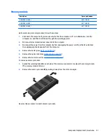
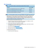


Heat sink assembly
NOTE:
The heat sink assembly spare part kits include replacement thermal materials.
Description
Spare part number
Heat sink for use in models with discrete graphics in the Carrizo-L and Beema chipsets
806760-001
Heat sink for use in models with discrete graphics in the Carrizo chipset
809105-001
Heat sink for use in models with UMA graphics in the Carrizo-L and Beema chipsets
806759-001
Heat sink for use in models with UMA graphics in the Carrizo chipset
809104-001
NOTE:
To properly ventilate the computer, allow at least
7.6 cm
(3.0 in) of clearance on the left side of the
computer. The computer uses an electric fan for ventilation. The fan is controlled by a temperature sensor
and is designed to turn on automatically when high temperature conditions exist. These conditions are
affected by high external temperatures, system power consumption, power management/battery
conservation configurations, battery fast charging, and software requirements. Exhaust air is displaced
through the ventilation grill located on the left side of the computer.
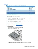
Before removing the heat sink assembly, follow these steps:
1.
Shut down the computer. If you are unsure whether the computer is off or in Hibernation, turn the
computer on, and then shut it down through the operating system.
2.
Disconnect all external devices connected to the computer.
3.
Disconnect the power from the computer by first unplugging the power cord from the AC outlet and
then unplugging the AC adapter from the computer.
4.
Remove the battery (see
Battery on page 29
).
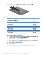
5.
Remove the optical drive (see
Optical drive on page 30
).
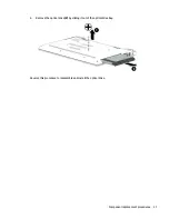
6.
Remove the bottom cover (see
Bottom cover on page 34
).
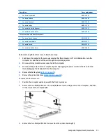
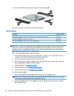
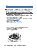
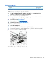
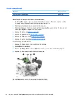
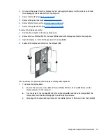
To remove the heat sink assembly:
1.
Position the system board upside down.
Component replacement procedures
43
Summary of Contents for Pavilion 2159m
Page 1: ...HP Pavilion Notebook AMD Maintenance and Service Guide ...
Page 4: ...iv Safety warning notice ...
Page 8: ...14 Recycling 97 Index 99 viii ...
Page 12: ...4 Chapter 1 Product description ...
Page 32: ...24 Chapter 3 Illustrated parts catalog ...
Page 40: ...32 Chapter 5 Removal and replacement procedures for Customer Self Repair parts ...
Page 80: ...72 Chapter 8 Using Setup Utility BIOS in Windows 8 1 ...
Page 88: ...80 Chapter 10 Backing up restoring and recovering in Windows 8 1 ...
Page 100: ...92 Chapter 12 Specifications ...
Page 104: ...96 Chapter 13 Power cord set requirements ...
Page 106: ...98 Chapter 14 Recycling ...
Page 110: ...102 Index ...


