2.7.1.5 Replacing a TFT7600 Power Supply
To replace a TFT7600 power supply, follow these steps:
Warning!
Ensure that the power to the unit is disconnected before removing the power supply. Failure to
do so can result in damage to the unit or personal injury.
1.
Extend the TFT7600 to the locked position.
2.
Disconnect the power supply cable from the rear of the unit.
3.
Disconnect the power cable from the PDU.
4.
Remove the power supply and replace (see callout 2 in
Figure 2-20
).
2.7.1.6 Moving the TFT7600 Rack-Mount Keyboard and Monitor Installed in a Rack
The TFT7600 is typically mounted and shipped with lock plates installed to prevent movement
or damage during transit. You must remove the lock plates to begin using the TFT7600. HP
recommends that you keep the original hardware in case you must move the rack with the
monitor installed. To install the lock plates and reverse the procedure to begin using the TFT7600,
follow these steps.
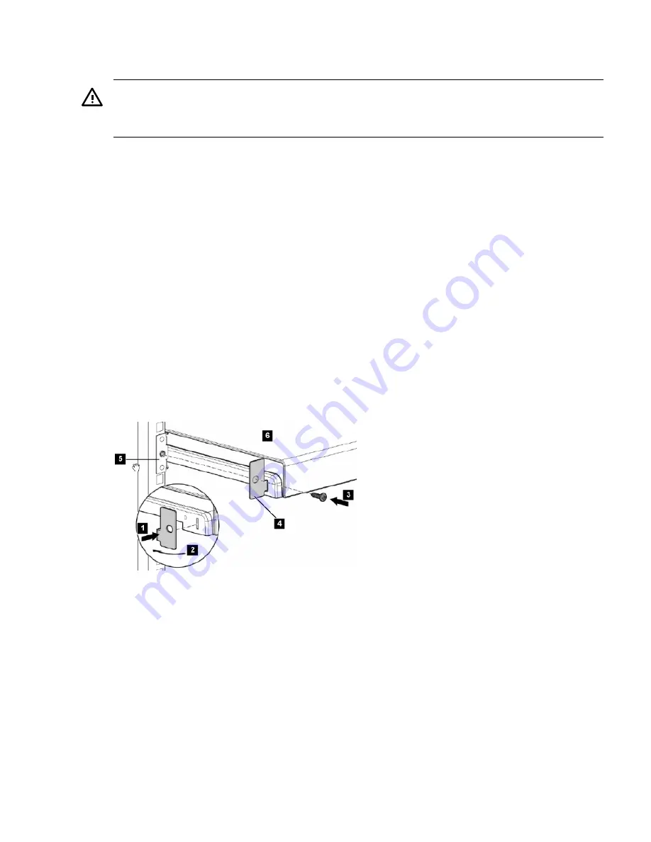
To install the lock plates:
1.
Place the lock plate in the slot and rotate back (see callouts 1 and 2 in
Figure 2-24
).
2.
Install one M6 screw (see callout 3) into the hole in the lock plate (see callout 4) and secure
it to the side rail (see callout 5).
3.
Repeat steps 1 and 2 to install the other lock plate.
Figure 2-24 TFT7600 Lock Plates
The following list corresponds to the callouts in
Figure 2-24
:
1.
Lock plate (left side)
2.
Rotating lock plate into place for mounting position
3.
M6 screw to fasten lock plate (left side shown)
4.
Lock plate correctly oriented and ready to fasten to rail
5.
Rail (left side shown)
6.
TFT7600
2.7.2 TFT5600 for Cluster Platform and SVA
A TFT5600 rack-mount keyboard and video monitor (KVM) provides direct local access to the
cluster. The TFT5600 (
Figure 2-25
) is connected to the administration node and to one other
service node. It is mounted in the utility rack. You must make this connection during system
installation, as described in
Section 3.2
.
2.7 KVM and Console Switches
51
Summary of Contents for Cluster Platform
Page 8: ...8 ...
Page 14: ...14 ...
Page 18: ...18 ...
Page 20: ...20 ...
Page 31: ...Figure 2 6 HP Modular Cooling System Front View 2 5 HP Modular Cooling System 31 ...
Page 62: ...62 ...
Page 70: ...70 ...
Page 72: ...72 ...
Page 76: ...76 ...
Page 82: ...82 ...
Page 87: ...87 ...
Page 88: ... A CPCCO 1F Printed in the US ...


