


WEBVISION™
55
95-7769—01
•
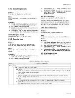
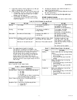
Fan fail
When configured with an air flow detector, the controller
protects equipment by disabling the system when the fan
fails
•
Changeover
The controller operates two-pipe FCUs configured with a
changeover input.
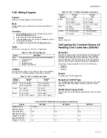
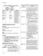
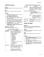
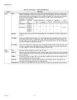
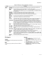
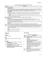
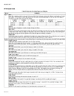
FCU Input/Output Specifications
Table 31 lists the FCU Input/Output specifications.
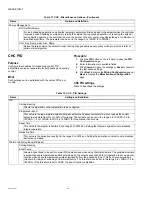
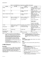
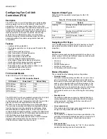
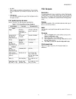
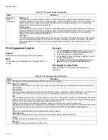
FCU Outputs
Description
FCU applications can have a variable number of heating and
cooling stages. The number of pipes used on the unit could be
two or four. The outputs could be of staged, PWM, floating, or
Thermal type. In addition the outputs can be of Change over
mode.
Purpose
Define the operation of the controller outputs and the type of
fan coil unit to be controlled.
Mode
Configuration can be performed with the wizard Off-line or
On-line.
Procedure
1.
Click the
Outputs
button on the left pane to open the
Output Configuration
page.
2.
Enter information into available fields.
3.
Click
Commit
to save the settings or
Reset
to revert to
the last saved settings.
4.
Click
Next
to display the
Input Configuration
page.
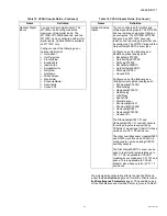
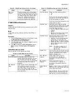
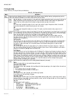
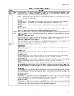
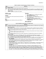
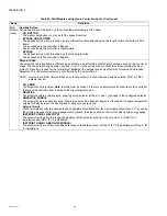
FCU Outputs fields
Table 32 on page 56 lists the FCU Outputs fields and
definitions.
Table 31. FCU Input/Output Specifications.
Input/Output
Function
Characteristic
Inputs
Digital
Window/
occupancy/
changeover/air
flow
Closed
≤
400 ohm,
open
≥
10K ohm
Analog/Digital
(Wall Module
connection only)
Fan speed/
Override
Resistor Network
Analog
Temperature
Sensor
20K ohm NTC
Analog
(Wall Module
connection only)
Setpoint
adjustment
10k Ohm
Outputs
Digital
(Wall Module
connection only)
Override LED
0/5 Vdc
Triac (2 pairs)
(See Table 30 for
options)
Heat and cool
24 Vac, 250 mA
max. continuous,
650 mA max. surge
(
≤
30 sec)
Relay (3)
Fan Switching
20 to 253 Vac, 3A
max.
High Power relay
(W7725D, F only)
Electric heat
(resistive load)
20 to 300 Vac, 10A
max., 6A max.


