


WEBVISION™
43
95-7769—01
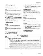
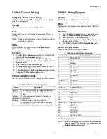
CHC Wiring Diagram
Purpose
Display the wiring diagram for the controller.
Mode
Configuration can be performed with the wizard Off-line or
On-line.
Procedure
1.
Click the
Wiring
button on the left pane to open the
Wiring Configuration
page.
2.
Enter information into available fields.
3.
Click
Commit
to save the settings or
Reset
to revert to
the last saved settings.
4.
Click
Back
to display the
PID Configuration
page.
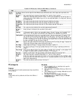
Fields
DI1 Window / Occupancy / Air Flow / Changeover.
LON Bus
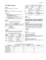
The terminals in Table 14 are used to connect the LON Bus
FTT-10A. The LON terminals are insensitive to polarity.
Power
24VAC: 50/60 Hz.
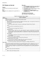
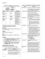
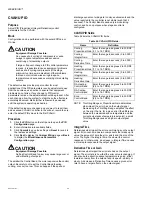
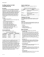
Configuring the Constant Volume Air
Handling Unit Controllers (CVAHU)
Description
The W7750 series is the Constant Volume Air Handling Unit
(CVAHU) controller in the Excel 10 family. It is a LonMark
compliant device designed to control single zone and heat
pump air handlers. The W7750 series can be configured to
control a wide variety of possible equipment arrangements.
The various models available for The XL10 CVAHU are:
• W7750A
• W7750B
• W7750C
Purpose
To configure a CVAHU application.
Navigating to CVAHU Pages
Go to the
Devices
tab. Expand the list of devices on the left
pane (listed under WebVision). Select a device to view its
properties.
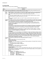
CVAHU Device Property Fields
Table 15 lists the CVAHU device properties for each controller
model.
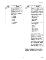
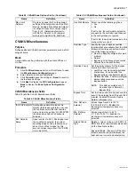
Table 13. CHC - Wiring Diagram.
Name
Definition
Wall
Module
Use these terminals to connect the Wall Module.
•
Override LED
•
Setpoint
•
Bypass Button
•
Room Temp Sensor
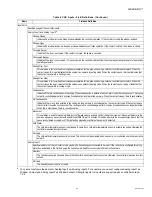
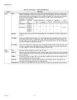
Table 14. CHC - LON Bus Terminals.
Output1 /
Output2
Terminal
14/15
Terminal
17/18
Floating
14 On = open valve
17 On = open valve
15 On = close valve
18 On = close valve
1-stage
14 = On/Off
17 = On/Off
15 = not used
18 = not used
2-stage
14 On = stage 1
17 On = stage 1
14 On + 15 On = stage 2
17 On + 18 On = stage 2
3-stage
14 On = stage 2
17 On = stage 1
15 On = stage 2
18 On = stage 2
14 On + 15 On = stage 3
17 On + 18 On = stage 3
PWM
14 = PWM
17 = PWM
15 = not used
18 = not used
Thermal
14 = Pulse Modulated
17 = Pulse Modulated
15 = not used
18 = not used
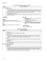
Table 14. CHC - LON Bus Terminals. (Continued)
Output1 /
Output2
Terminal
14/15
Terminal
17/18
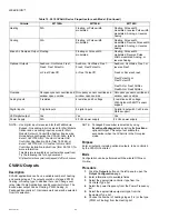
Table 15. XL10 CVAHU Device Properties for each Model.
Criteria
W7750A
W7750B
W7750C
Digital Outputs
6 (Relay)
8
5
Analog Outputs
0
0
3
Conventional or
Heat pump control
yes
yes
yes
Stages of electric or
gas fired heating
1-4
1-4
1-4
Stages of Cooling
1-4
1-4
1-4


