background image

WEBVISION™

95-7769—01

28

10.

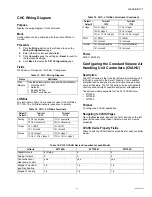
Type the user name and password and click 

Next

.

The same credentials are used while enabling dial in 

settings in WebVision.

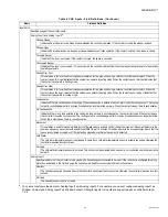
Fig. 41. Internet Account Information - User Name and 

Password.

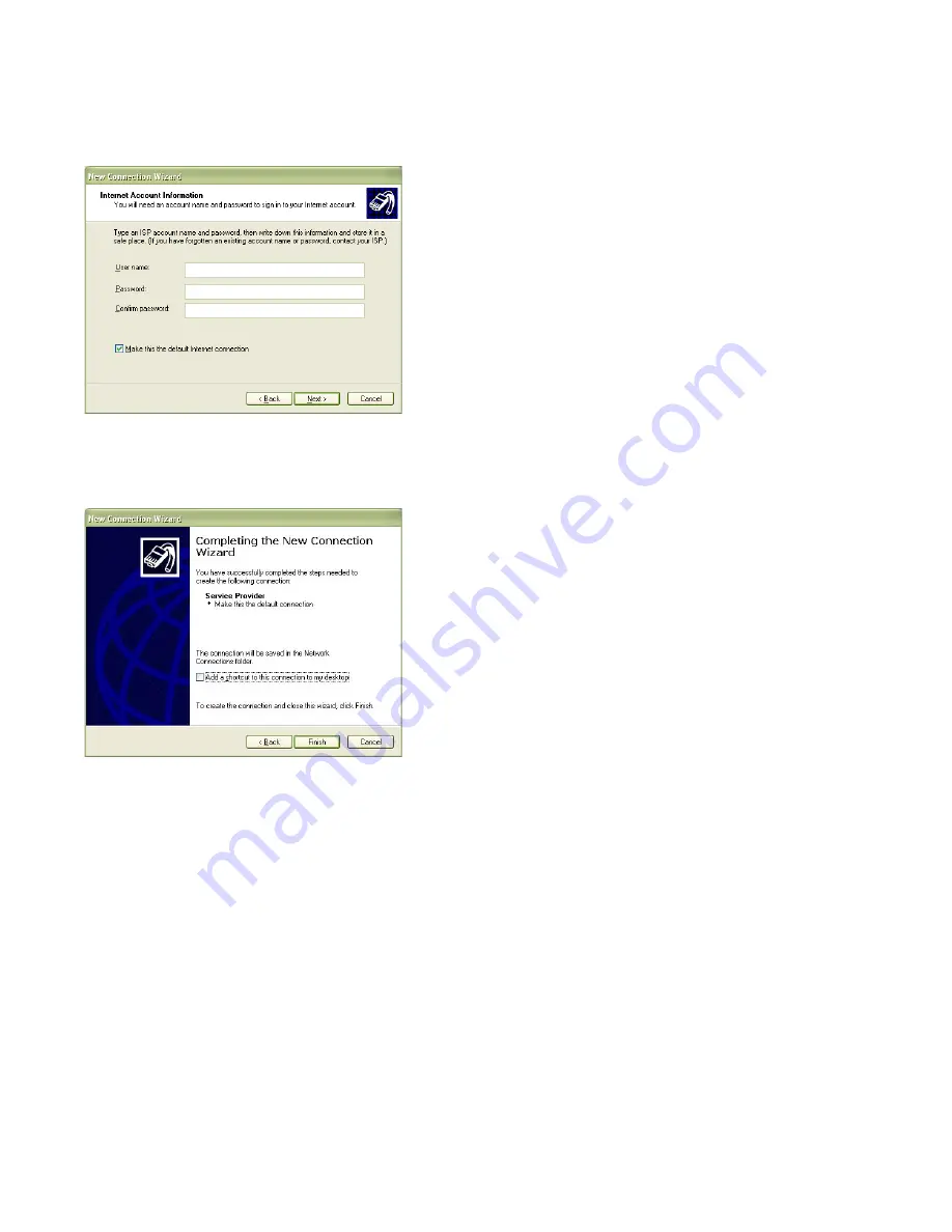
11.

Click 

Finish

 to complete the connection. 

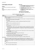
Fig. 42. Completing the New Connection Wizard screen.

To configure E-mail setup:

Complete the following procedure to configure the e-mail 

setup details:

1.

Click the 

Systems

 tab. The 

System

 page with General 

Properties appears.

2.

Click the 

Email Setup

 tab. The 

Email Setup

 page 

appears.

3.

Enter the following details:

• SMTP Server

Enable Email Service

: Check this box to enable 

the SMTP protocol.

Use Sever WebVision as SMTP gateway

Check this box to use WebVision server as 

SMTP gateway.

Email Server

: Enter the SMTP e-mail server to 

use this service.

You must configure SMTP e-mail server to send 

alarm notifications. The Internet Service Provider 

(ISP) or Network Administrator has to provide the 

server and domain names prior to configuring the 

SMTP E-mail server option. An example to 

maintain the format: SMTP.server.com.

Email Address

: Enter a valid e-mail address. 

The account must be present in the SMTP 

server.

User Authentication

: Check this box to provide 

the user credentials. On selection it enables the 

following parameters.

User Name

: Type the user name of the SMTP 

server. Type any name of your choice. For 

example, webvision1.

Password

: Type the SMTP password.

Confirm Password

: Retype your password.

NOTE: The password field cannot be empty. The maximum 

number of characters is 50. The characters allowed 

are: a-z, A-Z, 0-9, _, !, @, #, $, %, ^, *, -, |, SPACE.

4.

Click 

Save

 to save the settings.

5.

Click 

Send Test Mail

. The 

Email Service Status


displays the status. A test message is sent to the e-mail 

address. A confirmation message appears.

6.

If the settings are incorrect then, the

 Last Failure 

Message 

field displays the reason for failing in sending 

the message.

Configuring Admin

These files have .dist as the file extension. You can upload 

files up to 5MB in size.

Complete the following procedure to install a new package:

1.

Click 

Browse

 to upload the 

Software Update Package

This allows you to install software updates, if any, that 

are published by Honeywell for WebVision. 

2.

Click 

Install

.

Reboot WebVision

1.

Click the 

Reboot

 button to reboot WebVision. This logs 

you out and then initiates reboot.

2.

Re-logon after 5 to 10 minutes after the reboot is 

completed.

Backup Configuration

The backup file has .dist as the file extension.

Complete the following procedure to backup the configuration 

settings:

1.

Click 

Backup Configuration

 to backup the 

configuration settings.

2.

A window appears prompting you to 

Save

 the backup 

file.

3.

Click 

Save

 to save the backup file and specify the 

location for the file.

or

Click 

Cancel

 to close the pop-up.

Restore Configuration

You can restore the backed up files using this feature. The 

backup file has .dist as the file extension.

Complete the following procedure to restore the configuration 

settings:


Summary of Contents for WebVision

Page 1: ...o acts like a network time master to synchronize time and date in devices connected to it with its own time and date or with the Internet time servers Its Device Discovery feature enables you to discover online devices You can manage users and control their access to different resources in the system The System Administrator can configure network settings site information settings system and contr...

Page 2: ...o WebVision 1 Type the WebVision web address URL in the Address field of Internet Explorer The WebVision Login page appears Fig 1 Login page 2 Type your WebVision login name in the User Name field 3 Type your Password 4 Click Login or press Enter The Properties page appears To log off from WebVision Click the Logout link located on the right top of your screen to log off from WebVision You are red...

Page 3: ... layout coupled with the placement of various devices within a building With the help of a graphic you can view the various devices installed in your building Fig 4 Graphics Tab There are 3 locations in the WebVision where you can view and setup graphics These are Network Tree WebVision Node Max 1 Graphic Network Tree Device Node One graphic for each device This is the default device graphic You c...

Page 4: ...ert Text button A Text Message box appears Fig 7 Text Message Box 2 Type the required text in the Edit Text field 3 Click Save to reflect the changes in the image NOTE To abort the action click Cancel To insert an external link 1 Click the Insert External Link button The Add Link dialog box appears Fig 8 Add Link dialog box 2 Select a link from the Link To drop down list You can select from Device...

Page 5: ...kly search the required Schedules Use one of the following filter options to search for the required schedule Schedule Name Current Occupancy State TIP To quickly search the schedules type the first letter of schedule name or occupancy state as the case may be in the Keyword text box and type This lists all the names starting with the first letter that you have written in the Keyword text box Sche...

Page 6: ...ns it to the current schedule 6 Click Finish to save the settings NOTE To abort the action click Cancel Define Special Event Holiday schedules and schedules for special events differ from the normal days You can define schedules for special events using WebVision NOTE You can define any number of special events in a schedule To define a schedule for special events 1 Click Special Event on the Prop...

Page 7: ...want to delete from the Schedules Name list 3 Click Delete A confirmation message appears 4 Click OK to confirm the deletion NOTE Click Cancel to cancel deletion TIP To delete all schedules at once check the All check box in the header and click Delete Replicate Schedule You can replicate one schedule at a time A maximum of 10 copies of the selected schedule can be replicated Click Replicate to re...

Page 8: ...edged return to normal time the priority of the alarm and so on To filter and view alarms 1 Click the Alarms tab The View Alarms page appears The following information appears in a tabular format Fig 15 Alarms Tab NOTE Select the check box in the header row to select all the listed alarms Alarm Name List of all alarm names Device Name Lists all devices on which alarms are set To view the details o...

Page 9: ...mbo box Example For Occupancy State you can select alarm value as Unoccupied in which case WebVision raises an alarm whenever the point has Unoccupied as its value Select Alarm value This option is available for enum and boolean values Select the required alarm value from the drop down list Limits High Limit Select or type the higher limit of a device beyond which an alarm is raised Low Limit Sele...

Page 10: ... Add Alarm E Mail Recipient page appears 4 Select the recipient type using the Select Recipient Type drop down list For an External recipient enter Recipient Name Name of the recipient Recipient E Mail ID E Mail ID of the recipient For an Internal recipient enter Select User Select the type of the user using the drop down list 5 Select the alarm priorities that must be informed to the recipient Ch...

Page 11: ...end Channel Name Trend Type Trend Name Device Name Point Name Point Group TIP To quickly search the trends type the first letter of the required filter criteria in the Keyword text box and type an asterisk This lists all the names starting with the first letter that you have written in the Keyword text box Plotting trends NOTES 1 A security warning message appears when you access the Trends page a...

Page 12: ...ected for plotting the same trend as compared to Periodic Sampling Change Tolerance is required only for numeric points Select a numeric point from the Select Point option and type a tolerance value after which the data logging begins Trend Limit Roll Over is the default selection This option trends the point forever Roll Over Indicates that the readings of sampling are generated continuously When...

Page 13: ...er account with contractor privileges that cannot be deleted The privileges cannot be altered This is to ensure that there is at least one contractor available in the system Facility Manager This role represents a Building Engineer who maintains HVAC equipment and monitors the system with the help of WebVision Tenant The user assigned to this role has limited access to WebVision The user with the ...

Page 14: ...ge Setpoints 52 P P X Table 3 Role Matrix Continued Privilege ID Privileges Depends On Contractor Facility Manager Tenant 60 System P P 61 General Configuration P P X 62 IP Network Configuration P X X 63 Mail Configuration P P X 64 Change System Date and Time P P X 65 Upgrade Firmware P X X 66 Reboot System P P X 67 Download System Load P P X 68 Download Audit Log P P X 69 Network Navigation P C C...

Page 15: ...Add User button The Properties page appears Fig 22 Add User Properties page 2 Enter the account information of the user User ID The unique user ID It must have a minimum of 6 characters TIP You can use a maximum of 30 characters and a minimum of 6 characters to set your user ID The permitted characters include a z A Z _ 0 9 The following characters are not allowed and User Name The user name Passw...

Page 16: ... the devices present in WebVision All the information related to name type status and so on is available To view the list of devices 1 Click the Devices tab The Device List page appears The following information appears in a tabular format Fig 24 Devices Tab Device List page TIP Use Filters to view the required list Use one of the following filter options to search for the required device Channel ...

Page 17: ...he network dialog box appears The discovered devices are displayed Fig 26 Devices Tab Device List Discover button 3 Select a channel on which you want to discover devices 4 Click Discover to start discovery Once the discovery is completed WebVision lists the discovered new devices on the left side list 5 If you want to match a discovered device against an existing device in WebVision select the di...

Page 18: ...evice list 3 Select the number of copies that you want to create using the Number of copies to be created selection field 4 Choose a prefix or suffix to name the replicated copy of the device Select the Prefix with or Suffix with option as required 5 Type a label name for the device in the Label text box 6 Click OK to save the settings NOTE Click Cancel to abort the action Device Binding Binding r...

Page 19: ... and add a maximum of fifty points to each point group To edit a point group 1 Select a name of the point group that you want to edit in the Point Groups drop down list 2 Click Edit Point Group The selected details of the Point Group are displayed Follow the procedure as explained in step 4 of To add a point group and make the required changes To delete a point group 1 Click the Devices tab The De...

Page 20: ...ave the settings Balancing This process helps the VAV devices to calibrate their flow sensors for better air flow control NOTE To perform balancing ensure that the VAV device is online To view the Balancing page 1 Click the Balancing tab The Balancing page appears 2 The following information is displayed in tabular format Device Name Name of the device Channel Name Name of the channel on which the...

Page 21: ...itten at once depending on the configuration of the load assignment Each load assignment is identified by a load assignment number ranging from 1 to 50 The following are the two types of loads that DLC sheds to maintain demand below the peak setpoint Off Continuous Loads Off Continuous loads are the first loads that are shed by DLC Once shed they are not restored immediately Loads marked as Off Co...

Page 22: ...2 The following information is displayed as read only text Setpoint Displays the setpoint value Current KW Displays the average power consumption of the total assigned load DLC Status Displays the current DLC status Four modes present are Disable Deadband Shed and Restore NOTE Use Filters to quickly search the required DLC mode Use one of the following filter options to search for the required loa...

Page 23: ...ppear 4 Modify the required fields as described in step 4 of To add a Load on page 23 5 Click Save to save the settings Assign Load It displays the status of an individual load assignment or all load assignments If the DLC load configuration is modified then the load assignment status is displayed as Normal WebVision restores all the load assignments immediately by Table 4 Load Shed Methods If you...

Page 24: ... System Utilization To configure the System general properties Use the following procedure to configure the system general properties 1 Click the Systems tab The General tab of the System page appears Fig 31 Fig 31 System Tab General Tab 2 Enter Select the following site details Properties WebVision Name The entered WebVision name is displayed Time and Date Settings Select the Time Format and Date...

Page 25: ...lue of each octet separated by a period for example 192 168 0 1 HTTP Port Enter the port number The default port number is 80 If the port number entered is other than 80 then you must type the application s URL followed by the port number For example http 199 63 24 224 81 Network Mask This is used to separate Network Address and Host Address from IP Address in an IP network For example IP address ...

Page 26: ...s IP address of remote machine where WebVision application is hosted User Name Type the user name Password Type the password Modem Setting Initialization String As specified in the specification of the modem used Baud Rate As specified in the specification of the modem used NOTE The default modem settings works for most of the modems If the modem is not working then change the configuration 5 Clic...

Page 27: ...tion manually button 6 Select the Connect using a dial up modem option and click Next Fig 37 Connect using a dial up modem button 7 Type the name of the service provider and click Next Fig 38 Connection Name Service Provider 8 Type your phone number and click Next Fig 39 Phone Number to Dial screen 9 Select the required option for connection availability and click Next Fig 40 Connection Availabili...

Page 28: ...n1 Password Type the SMTP password Confirm Password Retype your password NOTE The password field cannot be empty The maximum number of characters is 50 The characters allowed are a z A Z 0 9 _ SPACE 4 Click Save to save the settings 5 Click Send Test Mail The Email Service Status displays the status A test message is sent to the e mail address A confirmation message appears 6 If the settings are i...

Page 29: ...e considerations for de commissioning XL15A W7760A 1 Alarms Alarms in XL15A cannot be automatically transferred to WebVision Looking at the XL15A configuration in LonSpec manually create corresponding Alarms configuration in WebVision Follow the steps given in User Guide or Online help to understand how to create Alarms in WebVision 2 Trends Trends in XL15A cannot be automatically transferred to W...

Page 30: ...o drive the occupancy state of those controllers user should first unassign them from T7350 in LonSpec commission T7350 and the assigned controllers before configuring schedules in WebVision 2 If T7350 is acting as Network Time Master it has to be disabled from LONSpec and re commission T7350 The Network Time Master Functionality in WebVision has to be enabled Once enabled WebVision will synchroni...

Page 31: ...he Metric system FIXING RAPIDZONE CONFIGURATION ERRORS IN LONSPEC Due to a configuration error in RapidZone sites built in Rapidzone and migrated to LONSpec may have a configuration error for every XL15C controller W7760C As a result device upload step in WebVision causes problems To fix the configuration error use the following procedure 1 Open the configuration of each XL15C and go to Control Lo...

Page 32: ...ID to the same domain ID configured in LonSpec typically 2C 44 decimal The ID must be specified in Hex format Click Save to save the changes Fig 48 Channel Info Domain ID and Domain Length fields 4 Click the Devices tab and go to Device List screen 5 Click Discover A dialog box appears Select Channel as Channel 1 and click Discover A progress bar appears indicating the discovery progress 6 After t...

Page 33: ...ow the User Guide of the router to have the desired setup 6 It is recommended that all the device configurations and bindings are checked field by field to ensure that the migration was successful as expected If any information is found missing the user can retry upload operation of configuration bindings as applicable If that does not solve the problem user should manually fill in the missing inf...

Page 34: ...ure control using different heating and cooling sequences The controller is provided with default configuration settings from the factory and is fully operable on installation Using standard Echelon configuration tools the controller can be configured with job specific settings The TR21 and TR23 wall modules interface with the Chilled Ceiling Controllers and provide the following options setpoint ...

Page 35: ...tput Configuration page 2 Enter information into available fields 3 Click Commit to save the settings or Reset to revert to the last saved settings 4 Click Next to display the Input Configuration page CHC Output Fields Table 8 describes the field definitions Table 7 Input Output Detail I O Function PIN Number Characteristics INPUTS Digital Window occupancy changeover air flow condensation 4 Closed...

Page 36: ... only option Heat Mode The output is modulated open when heat energy is needed in the space Cool Mode The output is modulated open when cool energy is needed in the space it is also modulated to limit the cold water temperature above dew point temperature if enabled ChangeOver Mode The output is modulated open when heat or cool energy is needed in the space In Cool Mode the output is modulated to ...

Page 37: ...e Configures the functionality of the connected wall module Be careful that the features configured here are the same as the features available on the wall module device to be connected Space Temp Sensor Specify whether or not the controller is to be used with a space temperature sensor connected to its input Normally a space temperature sensor is used but in cases where the space temperature is s...

Page 38: ...e country of usage The temperature engineering unit used C or F is the setting made in WebVision when creating the new project That setting is used for the total project Note that the setpoint knob only affects the Occupied and Standby Setpoints The Unoccupied setpoint is not affected by the setpoint knob Note that Version C and D Chilled Ceiling controllers have an on board setpoint They cannot b...

Page 39: ...ion Indicates if there is no condensation in the ceiling As long as there is no condensation the contact is closed If the contact opens the controller closes the cooling output The cooling output is controlled again after 5 minutes if condensation is no longer detected When the contact closes there is no condensation Movement This selection is used for movement detector configuration where a close...

Page 40: ...Stage Off Time Define the minimum off time for control outputs configured for operation as staged outputs This setting is particularly useful for heat exchanger operation or compressor units Each stage of the controlled output stays off for the minimum period of time before the controller turns it on again The selectable range is 0 to 600 seconds Valve Runtime This configuration parameter has thre...

Page 41: ... Also specify dew point temperature setpoint and a safety band to be used in case the dew point calculation fails or a humidity sensor is not available These fields are not used when the controller is not configured for ceiling protection CHC Miscellaneous Purpose To configure energy management parameters Mode Configuration can be performed with the wizard Off line or On line Procedure 1 Click the...

Page 42: ...of optimum start algorithm Table 11 CHC Miscellaneous Options Continued Name Option and Definition Table 12 CHC PID Settings Name Setting and Definition PID Cooling Heating Allows the algorithm control parameters to be configured Proportional band This value is the temperature deviation between setpoint and space temperature which causes the control output to modulate from 0 to 100 of full range T...

Page 43: ...igure a CVAHU application Navigating to CVAHU Pages Go to the Devices tab Expand the list of devices on the left pane listed under WebVision Select a device to view its properties CVAHU Device Property Fields Table 15 lists the CVAHU device properties for each controller model Table 13 CHC Wiring Diagram Name Definition Wall Module Use these terminals to connect the Wall Module Override LED Setpoi...

Page 44: ...e Output Configuration page 2 Enter information into available fields 3 Select the appropriate controller type from the Controller Type list 4 Select the power frequency from the Power Frequency list 5 Select the appropriate equipment type from the Equipment Type list 6 Choose the number of heating stages 1 4 or the type PWM or Floating from the Heating list Heating N A Floating or Pulse width mod...

Page 45: ...to 4 stages HeatPWM HeatPWMRev HeatAO HeatAORev or HeatingFloating Cooling 1 to 4 stages 1 to 4 stages CoolPWM or CoolingFloating 1 to 4 stages CoolPWM CoolPWMRev CoolAO CoolAORev or CoolingFloating Economizer EconNone or EconFloating EconNone EconPWM or EconFloating EconNone EconPWM EconPWMRev EconAO EconAORev or EconFloating Optional Points OccStatus AuxEcon Free1 Free2 Free1PulseOn Free1PulseOf...

Page 46: ... enabled if heating cooling or Economizer is configured as PWM It consists of Zero Scale Full Scale and Period values to control PWM output type Table 18 Optional Points for XL10 CVAHU Name Definition Occupancy_Status Energized if the controller is currently in Occupied mode Free1 Network controller digital output Follows the input signal nviFree1 Turns on when nviFree1 is on Free2 Network control...

Page 47: ...0B Enhanced and W7750C have two resistive and two voltage inputs that can be configured The W7750C supports the OutdoorTemp20KNTC sensor type Configure one of the following as a Resistive optional analog point DschgTempPT3000 OutdoorTempPT3000 RtnTempPT3000 DschgTemp20KNTC OutdoorTemp20KNTC RtnTemp20KNTC Unused RAI Configure one of the following as a Voltage current optional analog point Rtn Humid...

Page 48: ...ting or cooling are configured C O R Fail Mode Changeover Relay For Heat Pump only fail mode Heating or Cooling This option determines which mode Heating or Cooling is activated on power failure to the C O R This item is available only if HeatPump was selected on the Output page Fan Control You can select one of the following fan control options Auto Auto cycles the fan with call for cooling and h...

Page 49: ... for Heating and MinCoolOn Off for Cooling 3 Enter information into available fields 4 Click Commit to save the settings or Reset to revert to the last saved settings 5 Click Next to display the Zone Options Configuration page or Back to display the Economizer Parameters Configuration page Table 22 CVAHU Economizer Fields Name Definition Enable Type Source of the economizer enable decision for det...

Page 50: ...ting See Excel 10 System Engineering manual for a discussion of the CVAHUs recovery ramp feature Max Recov Temp Maximum recovery ramp degrees per hour Enter a value from 6 through 20 for cooling 8 through 20 for heating See Excel 10 System Engineering manual for a discussion of the recovery ramp feature of the CVAHU Max Recov Oa Temp Maximum recovery Oa outside air temperature Enter value from 0 t...

Page 51: ...lds Continued Name Definition Use Wall Module Select one of the following options Yes No If set to Yes the wall module setpoints are used by the controller and those set in the configuration are ignored If set to No the setpoint values set in the configuration are used Override Type Specify the type of Bypass override functions that are available from the Wall Module s Override push button Select ...

Page 52: ... or discharge sensors or wiring are in noisy environments and the value reported to the controller is not stable such that it bounces The Control Band is used only in modulating control and has no purpose when staged control is configured CVAHU PID fields Table 26 lists the CVAHU PID fields NOTE Throttling Range or Proportional Gain determines what impact the error has on the output signal Decreas...

Page 53: ...ation can be performed with the wizard Off line or On line Procedure 1 Click the Wiring Diagram button on the left pane to open the Wiring Diagram Configuration page 2 Enter information into available fields 3 Click Commit to save the settings or Reset to revert to the last saved settings 4 Click Back to display the PID Configuration page CVAHU Wiring Terminals Table 28 lists the CVAHU Wiring term...

Page 54: ...clude a space temperature sensor however a remote C7068A return air sensor can also be used Supported Output Types Table 30 lists the supported output types for the FCU Controller Navigating to FCU Pages Go to the Devices tab Expand the list of devices on the left pane listed under WebVision Select a device to view its properties Sequences Heat and cool sequences can be selected to be active or no...

Page 55: ...k the Outputs button on the left pane to open the Output Configuration page 2 Enter information into available fields 3 Click Commit to save the settings or Reset to revert to the last saved settings 4 Click Next to display the Input Configuration page FCU Outputs fields Table 32 on page 56 lists the FCU Outputs fields and definitions Table 31 FCU Input Output Specifications Input Output Function ...

Page 56: ... mode When operating in the changeover mode the controller uses only the one valve for controlling both heating and cooling Use this configuration only when changeover operation is required Four Pipe A fan coil unit that has four pipes connected providing both heating and cooling at the same time The fan coil controller uses one output to control heating only and one output to control cooling only...

Page 57: ... commanded open or closed This type is on Terminals 14 15 and or 17 18 The run times for the actuator are configured in the Equipment Control tab Floating Mid A three point actuator that can be commanded open or closed on terminals 14 15 and or 17 18 The run times for the actuator are configured in the Outputs tab The Zero Energy Position no Heat and no Cool is the middle Position 50 The Cool Rang...

Page 58: ...twork Management Command Wink LED Occupancy The LED shows the effective Occupancy Mode On indicates effective Occupied or Bypass 1 Flash per Second indicates effective Standby Off indicates effective Unoccupied 4 Flashes indicates the Controller answers of the Network Management Command Wink LCD Display This mode is used only for a Wall Module with LCD Display The Display has following Symbols to ...

Page 59: ...ntroller operation If the contact is closed the window is closed Window Open Indicates if a window is opened An open window disables the controller operation If the contact is closed the window is open Occupied Sensor Indicates if the room is occupied While unoccupied the controller switches from the occupied operating setpoints to the standby operating setpoints If the contact is closed the space...

Page 60: ...o not cause the controller to operate incorrectly The status of this digital input is reported to the network for use as a free digital input if required It has no effect on the control algorithm Table 33 FCU Inputs Fields Continued Name Definition Table 34 FCU Equipment Control Options Name Definitions Output Options Defines the operating characteristics of the two valve actuator outputs Output 1...

Page 61: ...lectric heating has priority over a water heating valve for example as the first heating sequence Or use for electric heating control only Use higher settings for example 90 where water heating has priority over electric heating Or when electric heating is required during summer winter changeover periods Hysteresis Define the control output level Switch level Hysteresis at which the Reheat control...

Page 62: ...ge 2 Enter information into available fields 3 Click Commit to save the settings or Reset to revert to the last saved settings 4 Click Next to display the PID Configuration page or Back to display the Zone Control Configuration page FCU Miscellaneous fields Table 36 FCU Zone Control Options Name Definitions Temperature Setpoints Cooling Heating Occupied Setpoints during Occupied mode Setpoints can...

Page 63: ...ame Definitions PID Cooling Heating Proportional band This value is the temperature deviation between setpoint and space temperature which causes the control output to modulate from 0 to 100 of full range Range 2 DDC to 100 DDC 3 6 to 180 DDF for PID control respectively 1 3 to 100 DDC 2 3 to 180 DDF for P Control only Reset Time This value is the integral reset time in the range 0 to 3200 sec Set...

Page 64: ...Direct connection of thermal actuators Direct connection to fan switch Direct connection to electric heat Factory configured default parameters Wide range of supported valves and actuators Interlocks and time delays to protect equipment Slim design fits into narrow fan coil units Terminations all on one side allow controller to be positioned at back of fan coil unit Power supplied by power mains D...

Page 65: ...system when the fan fails for fan coil units with manual fan speed control Changeover The controller operates two pipe units configured with a changeover input HYD Inputs Outputs HYD Outputs Description HYD applications can have a variable number of heating and cooling stages The number of pipes used on the unit could be two or four The outputs could be of staged PWM floating or Thermal type In ad...

Page 66: ... heat option to minimize field wiring errors For two pipe applications you can select only the changeover option HEATING The output is modulated open when heat energy is needed in the space COOLING The output is modulated open when cool energy is needed in the space CHANGEOVER The output is modulated open when heat or cool energy is needed in the space OUTP_NOT_USED The output is not controlled by...

Page 67: ... actually connected otherwise the controller measures incorrect values NO The local space temperature sensor is not used This option must be selected when a sensor is not connected LED LCD Display This configuration defines whether a Wall Module with LED or a Wall Module with LCD Display is connected For the LED there is shown either the Override Status or the Effective Occupancy Status The LCD Di...

Page 68: ...t cannot be used with an external TR21 or TR23 setpoint device NO_KNOB The setpoint knob is ignored Note that this must be chosen if there is no setpoint knob connected to the controller to prevent the controller from reacting to incorrect setpoint values RELATIVE The setpoint knob is a relative knob showing only a setpoint shift as and changes to the configured setpoint ABSOLUTE_MIDDLE The setpoi...

Page 69: ...ostat switch When the contact closes this input indicates that the system can operate in cooling mode When the contact opens this input indicates that the system can operate in heating mode DI_CHANGEOVER_HEAT This selection is for local heat cool changeover operation for two pipe units using a switch or local thermostat switch When the contact closes the input indicates that the system can operate...

Page 70: ...s for both Outputs have the same meaning as described in the following text Valve Direction Define the operating direction of the valves for actuator types Floating PWM and Thermal DIRECT To open the valve is modulated from 0 to 100 REVERSE To open the valve is modulated from 100 to 0 Min Stage Off Time Define the minimum off time for control outputs configured for operation as staged outputs This...

Page 71: ...override button Override Priority Allocate priority between local wall module operations for example Bypass and commands from the building management central Choices are LAST WINS Last received input takes precedence It can be either the Bypass button or the Network signal NETWORK WINS The Network signal always takes precedence over the Bypass button Energy Management DLC Stpt Bump For load sheddi...

Page 72: ...outside which the outputs are switched to full operation to act as a boost function when space temperature deviates significantly from the desired setpoint These values also serve as a threshold for two point switching of thermal actuators The threshold can be set in the range 0 to 10 DDC 7 2 to 180 DDF If the threshold is set to 0 DDC the boost function is disabled Table 47 Hydronic PID Parameter...

Page 73: ...g Inputs and four Digital Inputs of RIO Specify up to six analog inputs four resistive and two voltage and four digital inputs Mode Configuration can be performed with the wizard Off line or On line Procedure 1 Click the Input_pane button on the left pane to open the Input Configuration page 2 Enter information into available fields 3 Click Commit to save the settings or Reset to revert to the las...

Page 74: ...date every 2 seconds 7 Click Back to display the RIO s Input Configuration page RIO Deltas fields Configuring the Unit Ventilator UV The W7753A is the Unit Ventilator Controller in the Excel 10 product line family The Unit Ventilator is a LonMark compliant device to monitor control HVAC equipment lighting and other miscellaneous loads in a distributed network Refer to Excel 10 W7753A Unit Ventilat...

Page 75: ...me editable Cooling Select one of the following Cooling types Cooling_Stage_1 Cooling_Stage_2 Cooling_PWM Cooling_Floating No_Cooling If you select Floating the Motor Speed field displays actuator speed in seconds If you select PWM the PWM Settings fields become editable Economizer Selection of Economizer mixed air damper actuator type None or packaged external economizer PWM or Floating Econo_Non...

Page 76: ...SmokeMonitor DirtyFilterIn ShutDown shuts down and disables automatic temperature control WindowOpen Monitor generic switch input to be sent out over the LonWorks Bus network CoilFreezeStat AqstatMakeTmpRise make on Temperature Rise AqstatBreakTmpRise break on Temperature Rise TimeClock DripPanFull locks out cooling when contacts are made EconEnable Economizer enabled when contacts are made Option...

Page 77: ...an control options On Off Select Off to allow for control circuits where when in heat mode the fan is directly controlled by an interlock control circuit not part of the Excel 10 controller which brings on the fan once the plenum temperature has risen above its thermostatic set point Smoke Control This value determines what the controller does when a smoke alarm occurs either from the digital inpu...

Page 78: ...lected in the Equipment Control Tab Ashrae Cycle When a unit ventilator is in the occupied mode it typically follows one of three operating cycles defined by the American Society of Heating Refrigeration and Air Conditioning Engineers Inc ASHRAE Cycle I Fixed 100 Outdoor Air Cycle II Variable Percentage of Outdoor Air with Minimum Position setting Cycle III Variable Outdoor Air Maintaining Constan...

Page 79: ...by cooling setpoint range 50 to 90 F 10 to 32 C Cooling Unoccupied Setpoint Enter Unoccupied cooling setpoint range 50 to 90 F 10 to 32 C HeatingOccupied Setpoint Enter Occupied heating setpoint range 50 to 90 F 10 to 32 C Heating Standby Setpoint Enter Standby heating setpoint range 50 to 90 F 10 to 32 C Heating Unoccupied Setpoint Enter Unoccupied heating setpoint range 50 to 90 F 10 to 32 C Use...

Page 80: ...ION Equipment Damage Possible Adjustments may cause large over or undershooting of setpoint The default values provide proper control for most systems UV PID Settings fields Override Priority Set the priority scheme for the Bypass override function You can select one of the following options Last Whichever was last to occur either the button was pushed or the network signal arrived Net The network...

Page 81: ... 9 000 Heating Throttling Range Throttling Range or Proportional Gain Determines what impact the error has on the output signal Decreasing the Throttling Range amplifies the effect on the error that is for a given error the difference between the measured space temperature and the current actual space temperature setpoint a small Throttling Range causes a higher output signal value Enter the range...

Page 82: ...listed under WebVision Select a device to view its properties Configuration Inputs Control Parameters PID Flow Pickup Miscellaneous Custom Wiring Wiring Diagram Purpose Define VAV configuration attributes for the Excel 10 VAV II controller Mode Configuration can be performed with the device On line or Off line Procedure Use Table 62 to configure the Excel 10 VAV II 1 Click the Configuration button...

Page 83: ...display NOTE The LCD Wall Module is supported by VAV devices of type Smart Actuator only whose version is v1 02 14 and above Morning Warmup Type Defines the control method the controller uses when the controller status is set to morning warm up Valid selections for this field are Fixed Flow The controller maintains a fixed air flow setpoint or damper position during the warm up period Modulating F...

Page 84: ...eheat Type Defines the type of reheat used by the controller There are two basic types of reheat available for the VAV Terminal VAV Terminal Reheat and Peripheral Reheat Valid selections for this field are No Reheat There is no local reheat associated with the VAV Terminal One Stage Reheat There is one stage of electric reheat associated with the VAV Terminal One triac output is required for this ...

Page 85: ...gorithm that the controller will apply to the VAV Terminal Valid selections for this field are No Fan There is no fan associated with this VAV Terminal Series Fan The fan supplied with this VAV Terminal is a series style configuration Parallel Fan Temp The fan supplied with this VAV Terminal is a parallel style configuration that will use temperature control for the fan operation VavParallelFlowCo...

Page 86: ...WM period is at this value the PwM device will position itself to the full position The minimum resolution of the time value is 0 1 seconds Table 62 Excel 10 VAV II Configuration Parameters Continued Name Definition Table 63 Excel 10 VAV II Analog and Digital Inputs Name Definition Analog Input Configuration Analog 1 NOTE If the wall module type is selected without the sensor option in the General...

Page 87: ...cify differential pressure and velocity for flow sensors Define the differential pressures and velocities for the flow sensors These values would be used to calculate the flow linearization values during the download sequence Mode Configuration can be performed with the device On line or Off line Procedure 1 Click the Flow Pickup button on the left pane to open the Flow Pickup Table page 2 Enter i...

Page 88: ...tions You can select Velocity change the velocity value and select Yes in Update Alternate Column to update the volume values Alternatively you can modify the volume values and update the velocity Update Alternate Column You can choose Yes If the other column needs to be modified No If the other column does not need to be modified Table 67 VAV II MIscellaneous Settings Name Definition Percent Max ...

Page 89: ...shall be installed in slot E on the control board of the frequency converter The converter can then be controlled monitored and programmed from the LONWORKS network Configuring NXVFD settings IMPORTANT NOTE After the option card is installed it is mandatory to make the following settings for Control Place and Frequency Reference 1 Selection of Control Place The NXVFD device can be controlled from ...

Page 90: ...figured in both Off line and On line modes from the wizard Procedure 1 Click on the Configuration tab of NXVFD to open the VFD Configuration screen 2 Enter information into available fields 3 Click Commit to save the settings or Reset to revert to the last saved settings NXVFD Drive Parameters fields Table 69 NXVFD Drive Parameters Point Name Min Value Max Value Typical Value Description Maximum S...

Page 91: ...cted to the digital input Poll Points The XL15C controller utilizes poll points as a means to retrieve data from other network devices Data retrieved by a poll point is available for linking to XL15C objects such as math functions control loops logic loops and start stop loops The XL15C polls each point every two seconds If the response is not received within ten seconds the poll is changed to onc...

Page 92: ...nds frequency must not be greater than 15 Hz Pulsemeter At the most two digital inputs can be configured as Pulsemeters If 2 DIS are configured as Pulsemeter power from both will be summed e Select an Engineering Unit The Engineering Unit list contains all the engineer ing units you can assign to a digital input Engineer ing Unit is enabled only for Input Kind of Maintained and Momentary and disab...

Page 93: ... algorithm The user configures control algorithm type PID or Non linear bias position of set point within the proportional band i e 0 or 50 direct reverse acting output which sensor and outputs to use throttling range integral time derivative time start up ramp time recovery reset and sequencer parameters set points minimum on off and bypass times DLC shed bump and lead lag Purpose Define up to te...

Page 94: ...LOOP_ALARM is set c Sequencer Stager Sequencer The sequencer configuration values x1 x2 y1 and y2 determine the conversion from the primary control loop EPID to the three sequencer analog outputs The sequencer takes the primary EPID analog output value and splits it to three separate analog outputs Each of the sequenced analog outputs ranges from 0 to 100 The uses are controlling heating economize...

Page 95: ...dialog box Digital Input 1 through 6 Select a Link Type and Link Name for digital inputs On Delay Time The delay in time for switching from one state to another before the output value switches to ON Off Delay Time The delay in time for switching from one state to another before the output value switches to OFF DCAO Digital Compare Analog Output Sets the output value to equal analog input_1 if dig...

Page 96: ... defined There are two pos sible analog outputs Click the down arrow to view the list of outputs Select each one one at a time and specify its attributes b Select the analog output from Select Output c Type a Output Name d Select the required output from the Output Kind field The Output Kind must be one of the following types for analog output Unconfigured Analog Digital e Select the Engineering U...

Page 97: ...lable fields 3 Click Commit to save the settings or Reset to revert to the last saved settings 4 Click Next to display the Keypad Display Configuration page T7350 General Configuration fields See Table 70 Table 70 T7350 General Configuration Fields Name Definition Thermostat Model The T7350 Communicating Subbase T7350CS comes in two models T7350H1009 and T7350H1017 T7350H1009 This subbase is the T...

Page 98: ...or will show invalid and there will be a sensor fail alarm Remote A remote humidity sensor can be hard wired to the thermostat Select this option when the humidity input is required from a remote sensor The thermostat is compatible to H7631A1000 0 to 10V or equivalent sensors Network Select this option when the humidity input is required over the network from other controllers You have to create a...

Page 99: ... keypad using the installer configuration Press the Run and Copy buttons simultaneously and navigate to the code You are presented with a number identified by C1 Enter the first 2 digits of the configuration ID that the wizard has generated Continue entering 2 digits each for C2 through C8 Save this code using the Run button The configuration in the thermostat is changed to that in the wizard The ...

Page 100: ...eat and modulating cool action 2 To have Mod heat heating pump enable relay and 1 stage of heating configure Heat Stages as Heat Enable Heat Action depends on the actuator connected and connect the relay W1 such that it turns the heating pump ON or OFF Aux DO Use this option to configure the auxiliary outputs The auxiliary DO can be configured for economizer Time Of Day or for dehumidification The...

Page 101: ...t for temperature fields as degrees Centigrade Clock Display Use this to configure the display mode of time in the thermostat 12 Hour AM PM Selecting this option will display the thermostat time in 12 hour format 24 Hour Selecting this option will display the thermostat time in 24 hour format System Switch Use this option to configure the system operation of the thermostat OFF When this option is ...

Page 102: ... is selected the thermostat reduces the effective cooling temperature setpoint by the amount spec ified by the user The dehumidify setpoint must be smaller than the difference between the cooling and heating occupied setpoints and the difference between the cooling and the heating standby setpoints When one of these setpoints change the wizard automatically adjusts the dehumid reset setpoint such ...

Page 103: ...inutes to get the space temperature to the target setpoint during recovery The T7300 series 1000 did a similar method Based on the heat and cool setpoints configured and the minimum and maximum ramp rates configured the wizard automatically calculates the lead time information for both cool and heat recovery ramps and displays it in this section NOTE This data is applicable when the unoccupied set...

Page 104: ...on is enabled only if the discharge air temperature input is configured in the General page This will enable the usage of the discharge air high limit Heating DAT Hi Limit This option is available only if the discharge air temperature input is configured in the General page and Enable Heating DAT Hi Limit is selected Cooling Selections Extended Fan Operation Use this option to configure the time f...

Page 105: ...atically modifies the heat and cool throttling ranges when the number of stages configured is changed Refer the following table for the default values of integral time values for different stages If you change the number of stages to zero the integral time remains unchanged A value of 0 means that the integral time is disabled Valid range is 100 to 5000 seconds 0 also is a valid value Values from ...

Page 106: ...ericWritable Standby Heat nciSetPnts standbyHeat NumericWritable Unoccupied Heat nciSetPnts unoccupiedHeat NumericWritable Current State nviTodEvent currentState EnumWritable Next State nviTodEvent nextState EnumWritable Time To Next State nviTodEvent timeToNextState NumericWritable DLC Shed nviDlcShed DlcShed EnumWritable Out Of Limits nvoStatus outOfLimits BooleanPoint Open Circuit nvoStatus ope...

Page 107: ...HC Status Mode nvoChcStatus mode EnumPoint Output Position 1 nvoChcStatus outputPosition1 NumericPoint Output Position 2 nvoChcStatus outputPosition0 NumericPoint Primary Heat Output nvoUnitStatus heatOutputPrimary NumericPoint RO LED nvoChcStatus rOLed EnumPoint Reheat Active nvoChcStatus reheatActive EnumPoint Reset Bypass Time nvoChcStatus restBypassTime NumericPoint Scheduled Occupancy nvoChcS...

Page 108: ... Out Of Service X False or True Mechanical Fault X False or True Feedback Failure X False or True Over Range X False or True Under Range X False or True Electrical Fault X False or True Unable To Measure X False or True Command Failure X False or True Self Test Failed X False or True Application Mode X X X X Default Auto Heat Morning Warmup Cool Night Purge Pre cool Off Test Emergency Heat Fan Onl...

Page 109: ...larm Alarm Notify Enabled Alarm Notify Disabled Manual Control Remote Control Program Clear Reset Reset Manual Occupancy X X X X Default Occupied Unoccupied Bypass Standby Temporary Setpoint X X X X Units ºC Precision 1 Min 10 0 Max 35 0 Effective Setpoint X X X Units ºC Precision 1 Min 273 2 Max 327 7 Table 75 CHC Application of Points Continued Point Name Graphics Alarms Trends Commandable Inter...

Page 110: ...ff Frost Invalid Setpoint Temperature Sensor Alarm Type continued X X X Failed Setpoint Knob Failed Fan Speed Switch Failed Fan Failure SpaceTemp Com Failed HVAC Mode Com Failed Setpoint Offset Com Failed Sched Occ Com Failed DLC Communication Failed Relative Humidity Com Failed Outdoor Temp Com Failed Occ Sensor Com Failed Window Com Failed Manual Heat Com Failed Manual Cool Com Failed Cool Temp ...

Page 111: ...ctive or Active Fan Feedback X X X Failure or Running Fan Output X X X Units Precision 1 Min 163 8 Max 163 8 Fan Stages Active X X X Fan Off Fan Speed 1 Fan Speed 2 Fan Speed 3 Fan Auto Fan Default HW Override X X X Default Occupied Unoccupied Bypass Standby HW Window Open X X X Closed or Open Humidity X X X Units RH Precision 1 Min 163 8 Max 163 8 Manual Occupancy X X X Default Occupied Unoccupie...

Page 112: ...y Test Mode Floating Out of Sync Fan Switch Off Startup Wait Output Position 1 X X X Units Precision 1 Min 163 8 Max 163 8 Output Position 2 X X X Units Precision 1 Min 163 8 Max 163 8 Primary Heat Output X X X Units Precision 1 Min 163 8 Max 163 8 RO LED X X X Default Occupied Unoccupied Bypass Standby Reheat Active X X X Default Off Low Medium High On Reset Bypass Time X X X Units min Precision ...

Page 113: ...ision 1 Min 163 8 Max 163 8 Sensor Occupancy X X X Default Occupied Unoccupied Bypass Standby Space Temperature X X X Units ºC Precision 1 Min 273 2 Max 327 7 Terminal Load X X X Units Precision 1 Min 163 8 Max 163 8 Table 75 CHC Application of Points Continued Point Name Graphics Alarms Trends Commandable Internal Use Valid Values ...

Page 114: ...s InputNvFail EnumPoint Invalid Setpoint nvoAlarmStatus InvalidSetPoint EnumPoint Low Limit Economizer Close nvoAlarmStatus LowLimEconClose EnumPoint Node Disabled nvoAlarmStatus NodeDisabled EnumPoint Sensor Failure nvoAlarmStatus SensorFailure EnumPoint Application Mode nviApplMode hvacMode EnumWritable Manual Mode nviManualMode manMode EnumWritable Manual Occupancy State nviManOcc occupancy Enu...

Page 115: ... EnumPoint Outdoor Enthalpy nvoData2 OutdoorEnthalpy NumericPoint Outdoor Humidity nvoData2 OutdoorHumidity NumericPoint Outdoor Temperature nvoData2 OutdoorTemp NumericPoint Proof of Air Flow nvoData1 ProofAirFlow EnumPoint Return Air Enthalpy nvoData2 ReturnEnthalpy NumericPoint Return Air Humidity nvoData2 ReturnHumidity NumericPoint Return Air Temperature nvoData2 ReturnTemp NumericPoint Sched...

Page 116: ...ccupied Bypass Standby Time To Next State X Units min Precision 0 Min 0 0 Max 65535 0 DLC Shed X dlNoDlcShed dlMinDlcShed Air Flow Loss X False True Coil Freeze State X False or True Dirty Filter X False or True Frost Protect Alarm X False or True Indoor Air Quality Override X False or True Input Nv Fail X False or True Invalid Setpoint X False or True Low Limit Economizer Close X False or True No...

Page 117: ... Occupied Unoccupied Bypass Standby Temporary Setpoint X X X X Units ºC Precision 1 Min 10 0 Max 35 0 Fan Mode X X X X Fan Auto Fan Continuous Auxiliary Economizer Out X X X Off or On Bypass Timer X X X Units min Precision 0 Min 0 0 Max 65535 0 Calculated Outdoor Air Enthalpy X X X Units BTU lb Precision 1 Min 256 0 Max 256 0 Calculated Return Air Enthalpy X X X Units BTU lb Precision 1 Min 256 0 ...

Page 118: ...Out Fan On Auxiliary Economizer Out Economizer Floating Sync DLC Shed IAQ Override Smoke Monitor Window Open Dirty Filter Shutdown Monitor Switch Wshp Enable Coil Freeze State Update No 1 Data2 Field No X X X Update All 2 Bypass Timer Temperature Control Point Space Temperature Discharge Air Temperature Discharge Air Setpoint Return Air Temperature Return Air Humidity Return Air Enthalpy Outdoor A...

Page 119: ...tpoint X X X Units ºC Precision 1 Min 273 2 Max 327 7 Fan Status X X X Off or On Filter Air Pressure X X X Units in wc Precision 1 Min 32 0 Max 32 0 Free1 Out X X X Off or On Free2 Out X X X Off or On Heat Percent X X X Units Precision 1 Min 163 8 Max 163 8 Heat Position X X X Units Precision 0 Min 128 0 Max 127 0 Heat Stages On X X X Units null Precision 0 Min 0 0 Max 7 0 Indoor Air Quality Overr...

Page 120: ...cy Status Out X X X Off or On Occupancy Time Clock X X X Default Off Low Medium High On Outdoor Enthalpy X X X Units mA Precision 1 Min 256 0 Max 256 0 Outdoor Humidity X X X Units Precision 1 Min 0 0 Max 127 5 Outdoor Temperature X X X Units ºF Precision 1 Min 256 0 Max 256 0 Proof of Air Flow X X X Default Off Low Medium High On Return Air Enthalpy X X X Units mA Precision 1 Min 256 0 Max 256 0 ...

Page 121: ...X False or True Space Co2 X X X Units ppm Precision 0 Min 0 0 Max 65535 0 Space Temperature X X X Units ºF Precision 1 Min 256 0 Max 256 0 Temperature Control Point X X X Units ºF Precision 1 Min 256 0 Max 256 0 Water Source Heat Pump Enable X X X False or True Window Open X X X Closed or Open Table 77 CVAHU Application of Points Continued Point Name Graphics Alarms Trends Commandable Internal Use...

Page 122: ...leanPoint Electrical Fault nvoStatus electricalFault BooleanPoint Unable To Measure nvoStatus unableToMeasure BooleanPoint Communication Failure nvoStatus commFailure BooleanPoint Fail Self Test nvoStatus failSelfTest BooleanPoint Self Test In Progress nvoStatus selfTestInProgress BooleanPoint Locked Out nvoStatus lockedOut BooleanPoint Manual Control nvoStatus manualControl BooleanPoint Programmi...

Page 123: ... nvoUnitStatus coolOutput NumericPoint Economizer Output nvoUnitStatus econOutput NumericPoint Fan Output nvoUnitStatus fanOutput NumericPoint In Alarm nvoUnitStatus inAlarm NumericPoint Terminal Load nvoTerminalLoad levPercent NumericPoint Manual Mode nviManualMode ManualMode EnumPoint Table 78 FCU Points Details Continued Point Name Network Variable Field Point Type Table 79 FCU Application of P...

Page 124: ... Measure X False or True Communication Failure X False or True Fail Self Test X False or True Self Test In Progress X False or True Locked Out X False or True Manual Control X False or True Programming Failed X False or True Application Mode X X X X Default Auto Heat Morning Warmup Cool Night Purge Pre cool Off Test Emergency Heat Fan Only Free Cool Ice Maximum Heat Economy Dehumidify Calibrate Em...

Page 125: ...d Alarm Notify Disabled Manual Control Remote Control Program Clear Reset Reset Manual Occupancy X X X X Default Occupied Unoccupied Bypass Standby Temporary Setpoint X X X X Units ºC Precision 1 Min 10 0 Max 35 0 Effective Setpoint X X X Units ºC Precision 1 Min 273 2 Max 327 7 Table 79 FCU Application of Points Continued Point name Graphics Alarms Trends Commandable Internal Use Valid Values ...

Page 126: ...isabled No Alarm Node Off Frost Invalid Setpoint Temperature Sensor Failed Setpoint Knob Failed Fan Speed Switch Failed Fan Failure SpaceTemp Com Failed HVAC Mode Com Failed Setpoint Offset Com Failed Sched Occ Com Failed DLC Communication Failed almComfailTempreset Outdoor Temp Com Failed Occ Sensor Com Failed Window Com Failed Manual Heat Com Failed Manual Cool Com Failed almHwSwMismatch almRese...

Page 127: ...ed 1 Fan Speed 2 Fan Speed 3 Fan Auto Fan Default HW Override X X X Default Occupied Unoccupied Bypass Standby HW Window Open X X X Closed or Open In Alarm X X X False or True Manual Occupancy X X X Default Occupied Unoccupied Bypass Standby Unit Status Mode X X X Default Auto Heat Morning Warmup Cool Night Purge Pre cool Off Test Emergency Heat Fan Only Free Cool Ice Maximum Heat Economy Dehumidi...

Page 128: ...ed Unoccupied Bypass Standby Reheat Active X X X Default Off Low Medium High On Reset Bypass Time X X X Units min Precision 0 Min 0 0 Max 65535 0 Scheduled Occupancy X X X Default Occupied Unoccupied Bypass Standby Secondary Heat Output X X X Units Precision 1 Min 163 8 Max 163 8 Sensor Occupancy X X X Default Occupied Unoccupied Bypass Standby Space Temperature X X X Units ºC Precision 1 Min 273 ...

Page 129: ...ctrical Fault nvoStatus electricalFault BooleanPoint Unable To Measure nvoStatus unableToMeasure BooleanPoint Communication Failure nvoStatus commFailure BooleanPoint Fail Self Test nvoStatus failSelfTest BooleanPoint Self Test In Progress nvoStatus selfTestInProgress BooleanPoint Locked Out nvoStatus lockedOut BooleanPoint Manual Control nvoStatus manualControl BooleanPoint Fan Speed nviFanSpeedC...

Page 130: ...activeSetPt NumericPoint Space Temperature nvoHydStatus spaceTemp NumericPoint Reset Bypass Time nvoHydStatus restBypassTime NumericPoint Terminal Load nvoTerminalLoad levPercent NumericPoint Manual Mode nviManualMode ManualMode EnumPoint Table 80 HYD Point Details Continued Point Name Network Variable Field Name Point Type Table 81 HYD Application of Points Point name Graphics Alarms Trends Comma...

Page 131: ...e or False Unable To Measure X True or False Communication Failure X True or False Fail Self Test X True or False Self Test In Progress X True or False Locked Out X True or False Manual Control X True or False Application Mode X X X X Default Auto Heat Morning Warmup Cool Night Purge Pre cool Off Test Emergency Heat Fan Only Free Cool Ice Maximum Heat Economy Dehumidify Calibrate Emergency Cool Em...

Page 132: ...d Alarm Notify Disabled Manual Control Remote Control Program Clear Reset Reset Manual Occupancy X X X X Default Occupied Unoccupied Bypass Standby Temporary Setpoint X X X X Units ºC Precision 1 Min 10 0 Max 35 0 Effective Setpoint X X X Units ºC Precision 1 Min 273 2 Max 327 7 Table 81 HYD Application of Points Continued Point name Graphics Alarms Trends Commandable Internal Use Valid Values ...

Page 133: ...rm Node Off Frost Invalid Setpoint Temperature Sensor Failed Setpoint Knob Failed Fan Speed Switch Failed Fan Failure SpaceTemp Com Failed HVAC Mode Com Failed Setpoint Offset Com Alarm Type continued X X X Failed Sched Occ Com Failed DLC Communication Failed almComfailTempreset Outdoor Temp Com Failed Occ Sensor Com Failed Window Com Failed Manual Heat Com Failed Manual Cool Com Failed almHwSwMis...

Page 134: ... 1 Fan Speed 2 Fan Speed 3 Fan Auto Fan Default HW Override X X X Default Occupied Unoccupied Bypass Standby HW Window Open X X X Closed or Open In Alarm X X X False or True Manual Occupancy X X X Default Occupied Unoccupied Bypass Standby Unit Status Mode X X X Default Auto Heat Morning Warmup Cool Night Purge Pre cool Off Test Emergency Heat Fan Only Free Cool Ice Maximum Heat Economy Dehumidify...

Page 135: ...ed Unoccupied Bypass Standby Reheat Active X X X Default Off Low Medium High On Reset Bypass Time X X X Units min Precision 0 Min 0 0 Max 65535 0 Scheduled Occupancy X X X Default Occupied Unoccupied Bypass Standby Secondary Heat Output X X X Units Precision 1 Min 163 8 Max 163 8 Sensor Occupancy X X X Default Occupied Unoccupied Bypass Standby Space Temperature X X X Units ºC Precision 1 Min 273 ...

Page 136: ...int Digital In 1 nvorioIO di1 EnumPoint Digital In 2 nvorioIO di2 EnumPoint Digital In 3 nvorioIO di3 EnumPoint Digital In 4 nvorioIO di4 EnumPoint Digital Out 1 nvorioIO d01 EnumPoint Digital Out 2 nvorioIO d02 EnumPoint Digital Out 3 nvorioIO d03 EnumPoint Digital Out 4 nvorioIO d04 EnumPoint Digital Out 5 nvorioIO d05 EnumPoint Digital Out 6 nvorioIO d06 EnumPoint Digital Out 7 nvorioIO d07 Enu...

Page 137: ...gital In 3 X X X False or True Digital In 4 X X X False or True Digital Out 1 X X X Off or On Digital Out 2 X X X Off or On Digital Out 3 X X X Off or On Digital Out 4 X X X Off or On Digital Out 5 X X X Off or On Digital Out 6 X X X Off or On Digital Out 7 X X X Off or On Digital Out 8 X X X Off or On Mode X X X Startup Wait Heat Cool Off Disabled Emergency Heat Smoke Emergency Freeze Protect Man...

Page 138: ... EnumPoint Invalid Setpoint nvoAlarmStatus InvalidSetPt EnumPoint Low Limit Economizer Close nvoAlarmStatus LowLimEconClose EnumPoint Node Disabled nvoAlarmStatus NodeDisable EnumPoint Outside Air Quality nvoAlarmStatus OAQuality EnumPoint Sensor Failed nvoAlarmStatus SensorFail EnumPoint Application Mode nviApplicMode hvacMode EnumWritable Manual Mode nviManualMode manMode EnumWritable Manual Occ...

Page 139: ... NumericPoint Outside Air Quality nvoData2 OutsideQuality NumericPoint Override nvoData1 OverRide EnumPoint Proof Of Air Flow nvoData1 ProofAirFlow EnumPoint Return Air Enthalpy nvoData2 ReturnEnthalpy NumericPoint Return Air Humidity nvoData2 ReturnHumidity NumericPoint Return Air Temperature nvoData2 ReturnTemp NumericPoint Scheduled Occupancy nvoData1 SchedOcc EnumPoint Sensor Occupancy nvoData...

Page 140: ...cision 0 Min 0 0 Max 65535 0 DLC Shed X dlNoDlcShed dlMinDlcShed Air Flow Loss X false or true Communication Failed X false or true Dirty Filter X false or true Drip Pan Full X false or true Freeze State X false or true Frost Protect X false or true Indoor Air Quality Override X false or true Invalid Setpoint X false or true Low Limit Economizer Close X false or true Node Disabled X false or true ...

Page 141: ...cupancy X X X X Default Occupied Unoccupied Bypass Standby Temporary Setpoint X X X X Units ºC Precision 1 Min 10 0 Max 35 0 Auxiliary Economizer Out X X X Off or On Bypass Timer X X X Units min Precision 0 Min 0 0 Max 65535 0 Calculated Outdoor Enthalpy X X X Units BTU lb Precision 1 Min 256 0 Max 256 0 Calculated Return Air Enthalpy X X X Units BTU lb Precision 1 Min 256 0 Max 256 0 Coil Freeze ...

Page 142: ...mizer Enabled X X X Default Off Low Medium High On Economizer Float Synch X X X Off or On Economizer Position X X X Units Precision 0 Min 128 0 Max 127 0 Effective Occupancy X X X Default Occupied Unoccupied Bypass Standby Fan Speed X X X Units null Precision 0 Min 0 0 Max 7 0 Fan Switch X X X Default Off Low Medium High On Filter Pressure X X X Units in wc Precision 1 Min 32 0 Max 32 0 Free State...

Page 143: ... Startup Wait Heat Cool Off Disabled Smoke Emergency Freeze Protect Manual Factory Test Fan Only Monitor 1 X X X Units V Precision 1 Min 32 0 Max 32 0 Monitor Switch X X X Off or On Occupancy Statue Out X X X Off or On Occupancy Time Clock X X X Default Off Low Medium High On Outdoor Air Enthalpy X X X Units mA Precision 1 Min 256 0 Max 256 0 Outdoor Humidity X X X Units Precision 1 Min 0 0 Max 12...

Page 144: ... ºF Precision 1 Min 256 0 Max 256 0 Scheduled Occupancy X X X Default Occupied Unoccupied Bypass Standby Sensor Occupancy X X X Default Occupied Unoccupied Bypass Standby Shutdown X X X False or True Smoke Monitor X X X False or True Space CO2 X X X Units ppm Precision 0 Min 0 0 Max 65535 0 Space Temperature X X X Units ºF Precision 1 Min 256 0 Max 256 0 Effective Setpoint X X X Units ºF Precision...

Page 145: ...nsor Failed nvoAlarmStatus SensorFail EnumPoint Smoke Emergency nvoAlarmStatus SmokeEmergency EnumPoint Application Mode nviApplicMode hvacMode EnumWritable Manual Mode nviManualMode manMode EnumWritable Manual Occupancy nviManOcc occupancy EnumWritable Temporary Setpoint nviSetPoint tempP NumericWritable Auxiliary On nvoData AuxOn EnumPoint Box Flow nvoData uiBoxFlowS0 NumericPoint Box Flow Contr...

Page 146: ... OverRide EnumPoint Override IO nvoIO OverRide EnumPoint Peripheral Heat On nvoData PeriphHeatOn EnumPoint Peripheral Heat Position nvoData ubPeriphHeatPosS1 NumericPoint Reheat Percentage nvoData ubReheatPosS1 NumericPoint Scheduled Occupancy nvoData SchedOcc EnumPoint Sensor Occupancy nvoData SenOcc EnumPoint Space Temperature nvoData siSpaceTempS7 NumericPoint Space Temperature IO nvoIO siSpace...

Page 147: ...occupied Bypass Standby Next State X Default Occupied Unoccupied Bypass Standby Time To Next State X Units min Precision 0 Min 0 0 Max 65535 0 DLC Shed X dlNoDlcShed dlMinDlcShed Communication Failed X False or True Frost Protect X False or True Invalid Config X False or True Invalid Setpoint X False or True Node Disabled X False or True Sensor Failed X False or True Smoke Emergency X False or Tru...

Page 148: ...ndby Temporary Setpoint X X X X Units ºC Precision 1 Min 10 0 Max 35 0 Auxiliary On X X X Off or On Box Flow X X X Units L s Precision 0 Min 0 0 Max 65535 0 Box Flow Control Setpoint X X X Units L s Precision 0 Min 0 0 Max 65535 0 Box Heat Flow X X X Units L s Precision 0 Min 0 0 Max 65535 0 Bypass Timer X X X Units min Precision 0 Min 0 0 Max 65535 0 DLC Shed X X X Restored or Shed Damper Positio...

Page 149: ...100 0 Fan Status X X X Off or On Field No X X X Update All Fields Mode Effective Occupancy Override Scheduled Occupancy Network Manual Occupancy Sensor Occupancy Bypass Timer Temperature Control Point Space Temperature Discharge Temperature Supply Temperature Fresh Air Ratio Box Flow Cont Flow Sensor X X X Units ft min Precision 1 Min 4096 0 Max 4095 9 Flow Uncorrected X X X Units ft min Precision...

Page 150: ...l Flow Freeze Protect Factory Test IO Test Floating Out of Sync Disabled Manual Model X X X Units null Precision 0 Min 0 0 Max 3 0 Monitor Switch X X X Off or On Monitor Switch X X X Off or On Occupancy Sensor X X X Unoccupied Occupied Override X X X Default Occupied Unoccupied Bypass Standby Override IO X X X False or True Peripheral Heat On X X X Off or On Peripheral Heat Position X X X Units Pr...

Page 151: ...in 256 0 Max 256 0 Supply Temperature X X X Units ºF Precision 1 Min 256 0 Max 256 0 Temperature Sensor 0 X X X Units ºF Precision 1 Min 256 0 Max 256 0 Temperature Sensor 1 X X X Units ºF Precision 1 Min 256 0 Max 256 0 Effective Setpoint X X X Units ºF Precision 1 Min 256 0 Max 256 0 Window Open X X X Closed or Open Window Open IO X X X Closed or Open Table 87 VAV II Application of Points Contin...

Page 152: ...set Fault nviRstFault value NumericWritable Torque Reference Reference for PID nviProcessIn1 levPercent NumericWritable AC Fault Code nvoProcessOut8 levPercent NumericPoint Fault Active nvoDrvStatus bit3 BooleanPoint DC Link Voltage nvoProcessOut7 levPercent NumericPoint Drive Current nvoDrvCurnt amp NumericPoint Drive Energy nvoDrvEnrgy elecKwh NumericPoint Drive Power nvoDrvPwr powerKilo Numeric...

Page 153: ...X Units Precision 1 Min 0 0 Max 100 0 Torque Reference Reference for PID X X X X Units Precision 1 Min 163 8 Max 163 8 AC Fault Code X X X Units Precision 1 Min 163 8 Max 163 8 Fault Active X X X True or False DC Link Voltage X X X Units Precision 1 Min 163 8 Max 163 8 Drive Current X X X Units A Precision 1 Min 3276 8 Max 3276 7 Drive Energy X X X Units kW hr Precision 0 Min 0 0 Max 65535 0 Drive...

Page 154: ...Min 163 8 Max 163 8 Motor Voltage X X X Units Precision 1 Min 163 8 Max 163 8 Output Frequency X X X Units Precision 1 Min 163 8 Max 163 8 Reference Eq Actual X X X True or False Drive Run Hours X X X Units hr Precision 0 Min 0 0 Max 65535 0 Counter Clockwise X X X True or False Warning Active X X X True or False Table 89 NXVFD Application of Points Continued Point Name Graphics Alarms Trends Comm...

Page 155: ...int Nvo A I Cnt _ai Chan3 Sensor nvoAICnt data aiChan3Sensor NumericPoint Nvo A I Cnt _ai Chan4 Sensor nvoAICnt data aiChan4Sensor NumericPoint Nvo A I Cnt _ai Chan5 Sensor nvoAICnt data aiChan5Sensor NumericPoint Nvo A I Cnt _ai Chan6 Sensor nvoAICnt data aiChan6Sensor NumericPoint Nvo A I Cnt _ai Chan7 Sensor nvoAICnt data aiChan7Sensor NumericPoint Nvo A I Cnt _ai Chan8 Sensor nvoAICnt data aiC...

Page 156: ...urrent State temp ControlLoop_1 nviTodEventIn currentState EnumWritable Next State temp ControlLoop_1 nviTodEventIn nextState EnumWritable Time To Next State temp ControlLoop_1 nviTodEventIn timeToNextState NumericWritable Current State temp StartStopLoop_1 nviTodEventIn currentState EnumWritable Next State temp StartStopLoop_1 nviTodEventIn nextState EnumWritable Time To Next State temp StartStop...

Page 157: ...ercent temp ControlLoop_1 nvoFTStatus data seq3CmdPercent NumericPoint Nvo F T Status _prim Activ Stages temp ControlLoop_1 nvoFTStatus data primActivStages NumericPoint Nvo F T Status _seq1 Active Stages temp ControlLoop_1 nvoFTStatus data seq1ActiveStages NumericPoint Nvo F T Status _seq2 Active Stages temp ControlLoop_1 nvoFTStatus data seq2ActiveStages NumericPoint Nvo F T Status _seq3 Active ...

Page 158: ...atus data outStatus EnumPoint Nvo Bypass Arb _override Priority temp StartStopLoop_1 nvoBypassArb data overridePriority BooleanPoint Nvo Bypass Arb _wall Mod Override temp StartStopLoop_1 nvoBypassArb data wallModOverride EnumPoint Nvo Bypass Arb _bypass Timer temp StartStopLoop_1 nvoBypassArb data bypassTimer NumericPoint Nvo Bypass Arb _occ Timer temp StartStopLoop_1 nvoBypassArb data occTimer N...

Page 159: ... Status _ File Alm X False or True Nvo Alarm Status _ Input Rem Poll Alm X False or True Nvo Alarm Status _ Flash Chksum Alm X False or True Nvo Alarm Status _ Sensor Alm X False or True Nvo Alarm Status _ Input N V Alm X False or True Nvo Alarm Status _ St Pt Lp10 Alm X False or True Nvo Alarm Status _ St Pt Lp9 Alm X False or True Nci Flex Set Pts _occupied X X X X Units null Precision 1 Min inf...

Page 160: ... _value X X X Units Precision 1 Min 0 0 Max 100 0 Nvo Dig Cmd Free _state X X X Off On Default Nvo Appl Mode _hvac Mode X X X Default Auto Heat Morning Warmup Cool Night Purge Pre cool Off Test Emergency Heat Fan Only Free Cool Ice Maximum Heat Economy Dehumidify Calibrate Emergency Cool Emergency Steam Max Cool HVAC Load No Load Nvo Econ Enable _value X X X Units Precision 1 Min 0 0 Max 100 0 Nvo...

Page 161: ...s _effective Set Point X X X Units null Precision 1 Min inf Max inf Nvo F T Status _cntrl Sensor X X X Units null Precision 1 Min inf Max inf Nvo F T Status _reset Amount X X X Units null Precision 1 Min inf Max inf Nvo F T Status _bypass Remaining X X X Units null Precision 0 Min 0 0 Max 65535 0 Nvo F T Status _manual Mode X X X Enable Disable Manual Nvo F T Status _effect Occupancy X X X Occupie...

Page 162: ...255 0 Nvo F T Status _seq2 Cmd Percent X X X Units Precision 0 Min 0 0 Max 255 0 Nvo F T Status _seq3 Cmd Percent X X X Units Precision 0 Min 0 0 Max 255 0 Nvo F T Status _prim Activ Stages X X X Units null Precision 0 Min 0 0 Max 255 0 Nvo F T Status _seq1 Active Stages X X X Units null Precision 0 Min 0 0 Max 255 0 Nvo F T Status _seq2 Active Stages X X X Units null Precision 0 Min 0 0 Max 255 0...

Page 163: ...Nvo F T Status _seq3 Stage4 On X X X False or True Nvo F T Status _aux Status X X X Off or On Nvo L L Status _man Mode Status X X X Enable Disable Manual Nvo L L Status _or Gate Status X X X Off or On Nvo L L Status _dc Ao Status X X X Units null Precision 1 Min inf Max inf Nvo Bypass _value X X X Units Precision 1 Min 0 0 Max 100 0 Nvo Bypass _state X X X Off On Default Nvo St Stp Status _bypass ...

Page 164: ...Default Nvo Bypass Arb _bypass Timer X X X Units null Precision 0 Min 0 0 Max 65535 0 Nvo Bypass Arb _occ Timer X X X Units null Precision 0 Min 0 0 Max 255 0 Nvo Bypass Arb _schedule X X X X Occupied Unoccupied Bypass Standby Default Nvo Bypass Arb _occ Sensor X X X Occupied Unoccupied Bypass Standby Default Nvo Bypass Arb _man Override X X X Occupied Unoccupied Bypass Standby Default Nvo Bypass ...

Page 165: ...recision 0 Min 0 0 Max 65535 0 Nvo A I Cnt _ai Chan8 Sensor X X X Units null Precision 0 Min 0 0 Max 65535 0 Nvo A I Cnt _ai Calibration Chan1 X X X Units null Precision 0 Min 0 0 Max 65535 0 Nvo A I Cnt _ai Calibration Chan2 X X X Units null Precision 0 Min 0 0 Max 65535 0 Nvo A I Filtered Cnt _ai Chan1 Sensor X X X Units null Precision 0 Min 0 0 Max 65535 0 Nvo A I Filtered Cnt _ai Chan2 Sensor ...

Page 166: ...2 X X X Off or On Nvo D I Sensor _on Off3 X X X Off or On Nvo D I Sensor _on Off4 X X X Off or On Nvo D I Sensor _on Off5 X X X Off or On Nvo D I Sensor _on Off6 X X X Off or On Nvo D I Sensor _on Off7 X X X Off or On Nvo D I Sensor _on Off8 X X X Off or On Nvo Cal Cnt _ Cal Count0 X X X Units null Precision 0 Min 0 0 Max 65535 0 Nvo Cal Cnt _ Cal Count1 X X X Units null Precision 0 Min 0 0 Max 65...

Page 167: ... Temp _temp P X X X Units ºC Precision 1 Min 273 2 Max 327 7 Nvo Od Hum _lev Percent X X X Units Precision 1 Min 163 8 Max 163 8 Nvo Counter1 _count X X X Units null Precision 0 Min 0 0 Max 65535 0 Nvo Counter2 _count X X X Units null Precision 0 Min 0 0 Max 65535 0 Nvo Cascade Out _power Kilo X X X Units kW Precision 1 Min 0 0 Max 6553 5 Nvo Sensor Occ1 _occupancy X X X Occupied Unoccupied Bypass...

Page 168: ...EnumPoint Application Mode nviApplicMode hvacMode EnumWritable Manual Mode nviRequest objectRequest EnumWritable Manual Occupancy nviOccManCmd occupancy EnumWritable Temporary Setpoint nviSetpoint tempP NumericWritable Auxiliary Heat 1 nvoData2 noAuxHeat1 EnumPoint Auxiliary Heat 2 nvoData2 noAuxHeat2 EnumPoint Auxiliary Relay nvoData2 relayAux EnumPoint Auxiliary Relay nvoData2 auxRelay EnumPoint...

Page 169: ...rary Setpoint nvoData2 temporarySetPt NumericPoint Terminal Load nvoData1 terminalLoad NumericPoint Time To Next State nvoData2 scheduledTuncos NumericPoint Total Error nvoData2 totalError NumericPoint nviTimeSet year Numeric Writable nviTimeSet month Numeric Writable nviTimeSet day Numeric Writable nviTimeSet hour Numeric Writable nviTimeSet minute Numeric Writable nviTimeSet second Numeric Writa...

Page 170: ... or True Invalid IO Configuration X False or True Invalid SubBase Type X False or True Network Communication Failed X False or True Sensor Failed X False or True Application Mode X X X X Default Auto Heat Morning Warmup Cool Night Purge Pre cool Off Test Emergency Heat Fan Only Free Cool Ice Maximum Heat Economy Dehumidify Calibrate Emergency Cool Emergency Steam Max Cool HVAC Load No Load Fan Mod...

Page 171: ...X X Off or On Auxiliary Relay X X X Off or On Auxiliary Relay X X X Off or On Bypass Time X X X Units min Precision 0 Min 0 0 Max 65535 0 Cool Relay 1 X X X Off or On Cool Relay 2 X X X Off or On Cool Relay 3 X X X Off or On Cool Stages On X X X Units null Precision 0 Min 0 0 Max 255 0 DLC Shed X X X Restored or Shed Days Left Keypad Holiday X X X Units day Precision 0 Min 0 0 Max 255 0 Dehumidifi...

Page 172: ... or On Heat Stages On X X X Units null Precision 0 Min 0 0 Max 255 0 Holiday X X X False or True Next State X X X Occupied Unoccupied Bypass Standby Occ Null Occupancy Sensor X X X Unoccupied Occupied Outdoor Temperature X X X Units ºC Precision 1 Min 273 2 Max 327 7 Percent Cool Command X X X Units Precision 1 Min 163 8 Max 163 8 Percent Heat Command X X X Units Precision 1 Min 163 8 Max 163 8 Re...

Page 173: ... sbSubase4 sbSubase5 sbSubase6 sbSubase7 sbSubase8 sbSubase9 sbSubase10 sbSubase11 sbSubase12 sbSubase13 sbSubase14 sbSubase15 sbSubase16 System Mode X X X Default Auto Heat Morning Warmup Cool Night Purge Pre cool Off Test Emergency Heat Fan Only Free Cool Ice Maximum Heat Economy Dehumidify Calibrate Emergency Cool Emergency Steam Max Cool HVAC Load No Load Temporary Setpoint X X X Units ºF Prec...

Page 174: ...Min 163 8 Max 163 8 Time To Next State X X X Units min Precision 0 Min 0 0 Max 65535 0 Total Error X X X Units ºF Precision 1 Min 512 0 Max 512 0 Table 93 T7350 Application of Points Continued Point Name Graphics Alarms Trends Commandable Internal Use Valid Values ...

Page 175: ...uring Hydronic Controllers HYD 64 HYD Outputs 65 HYD Inputs 67 HYD Equipment Control Outputs 69 HYD Switching Levels 70 HYD Zone Control 70 HYD Miscellaneous Parameters 71 HYD PID 71 HYD Wiring 72 Configuring the Excel 10 Remote Input Output Device RIO 73 RIO Inputs 73 RIO Outputs 73 RIO Deltas 74 Configuring the Unit Ventilator UV 74 UV Outputs 75 UV Inputs 75 UV Equipment Control Options 76 UV E...

Page 176: ...ons U S Registered Trademark 2010 Honeywell International Inc 95 7769 01 M S 05 10 Printed in U S A LON LONWORKS LonMark and Echelon are registered trademarks of Echelon Corporation Microsoft Windows and Internet Explorer are registered trademarks of Microsoft Corporation Niagara Framework and the Niagara framework logo are registered trademarks of Tridium Inc WebVision and WebStat are trademarks ...

Reviews: