background image

8                             Receipt of Delivery


Honeywell


2

2.4     WARRANTY

Honeywell’s time of warranty is 30 months from the delivery or 24 months from the 
commissioning whichever expires first (General Conditions NL92/Orgalime S92 ).

Summary of Contents for SmartDrive Compact

Page 1: ...Ho Honeywell Complete User Manual SmartDrive Compact Constan and variable torque Variable Frequency Drives for Induction motors Subject to changes without notice ...

Page 2: ...d connections 13 3 2 1 Power cabling 13 3 2 2 Control cabling 14 3 2 3 Cable and fuse specifications 16 3 2 4 General cabling rules 17 3 2 5 Stripping lengths of motor and mains cables 18 3 2 6 Cable installation and the UL standards 18 3 2 7 Cable and motor insulation checks 19 4 COMMISSIONING 20 4 1 Commissioning steps of SmartDrive Compact 20 5 FAULT TRACING 22 6 SMARTDRIVE COMPACT CONTROL CONN...

Page 3: ...R P0 44 8 13 System parameters 44 9 PARAMETER DESCRIPTIONS 46 9 1 Motor settings Control panel Menu PAR P1 46 9 2 Start Stop setup Control panel Menu PAR P2 50 9 3 Frequency references Control panel Menu PAR P3 53 9 4 Ramps brakes setup Control panel Menu PAR P4 54 9 5 Digital inputs Control panel Menu PAR P5 58 9 6 Analoque inputs Control panel Menu PAR P6 59 9 7 Digital and analoque outputs Cont...

Page 4: ...ming into contact with this voltage is extremely dangerous and may cause death or severe injury The control unit is isolated from the mains potential 2 The motor terminals U V W T1 T2 T3 and the possible brake resistor terminals are live when inverter is connected to mains even if the motor is not running 3 The control I O terminals are isolated from the mains potential However the relay output te...

Page 5: ...s live if the motor is energized by the process In this case the motor functions as a generator feeding energy to the inverter 7 After disconnecting the inverter from the mains wait until the fan stops and the indicators on the display go out Wait 5 more min utes before doing any work on power connections ...

Page 6: ...sible to arise in fault situations 1 The SmartDrive Compact inverter has been designed for fixed installations only 2 Do not perform any measurements when the inverter is connected to the mains 3 Do not perform any voltage withstand tests on any part of Smart Drive Compact The product safety is fully tested at factory 4 Prior to measurements on the motor or the motor cable disconnect the motor cab...

Page 7: ...re that the machine connected to the motor allows the motor to be started Set the maximum motor speed frequency according to the motor and the machine connected to it Before reversing the motor shaft rotation direction make sure that this can be done safely Make sure that no power correction capacitors are connected to the motor cable ...

Page 8: ...re 2 1 SmartDrive Compact type designation code 2 2 STORAGE If the inverter is to be kept in store before use make sure that the ambient conditions are acceptable Storing temperature 40 70 C Relative humidity 95 no condensation 2 3 MAINTENANCE In normal operating conditions SmartDrive Compact inverters are maintenance free COMP400 1P1 20 Product range COMP SmartDrive Compact Nominal voltage 230 20...

Page 9: ... Receipt of Delivery Honeywell 2 2 4 WARRANTY Honeywell s time of warranty is 30 months from the delivery or 24 months from the commissioning whichever expires first General Conditions NL92 Orgalime S92 ...

Page 10: ...ION There are two possible ways to mount SmartDrive Compact in the wall either screw or DIN rail mounting The mounting dimensions are given on the back of the drive and on the following page Figure 3 1 Screw mounting Figure 3 2 DIN rail mounting MI2 3 MI1 M 4 M 5 1 2 ...

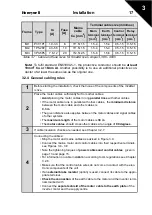
Page 11: ...free space shall be left above and below the inverter to ensure sufficient air circulation and cooling You will find the required dimensions for free space in the ta ble below Type H1 H2 H3 W1 W2 W3 D1 D2 MI1 156 5 147 137 3 65 5 37 8 4 5 98 5 7 MI2 195 183 170 90 62 5 5 5 101 5 7 MI3 262 5 252 3 241 3 100 75 5 5 108 5 7 Table 3 1 SmartDrive Compact dimensions in millimetres W1 W2 W3 H1 H2 D1 H3 D...

Page 12: ...ed for use in the 1st environment This EMC class is meant for highly sensitive areas and can be sometimes required in in stallations in e g hospitals or airport control towers NOTE The requirements of class C1 are fulfilled only as far as the conducted emis sions are concerned with an external EMC filter Category C2 Honeywell EMC class H All Honeywell SmartDrive Compact invert ers comply with the ...

Page 13: ...diate transformers to a low voltage power supply network which supplies buildings used for domestic purposes NOTE houses apartments commercial premises or offices in a residential building are examples of first environment locations Second environment Environment that includes all establishments other than those directly connected to a low voltage power supply network which supplies build ings use...

Page 14: ...tion 13 3 3 2 CABLING AND CONNECTIONS 3 2 1 Power cabling Note Tightening torque for power cables is 0 5 0 6 Nm Figure 3 4 SmartDrive Compact power connections MI1 Figure 3 5 SmartDrive Compact power connections MI2 MI3 ...

Page 15: ...14 Installation Honeywell 3 3 2 2 Control cabling Figure 3 6 Mount the PE plate and control cable support ...

Page 16: ...Honeywell Installation 15 3 Figure 3 7 Open the cover Figure 3 8 Install the control cables See Chapter 6 2 Strip the plastic cable coating for 360 Control cable tightening torque 0 4 Nm grounding ...

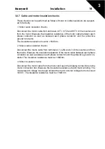
Page 17: ...ific mains voltage Shielded cable not required NKCABLES MCMK or similar recommended 2 Power cable equipped with concentric protection wire and intended for the specific mains voltage NKCABLES MCMK or similar recommended 3 Power cable equipped with compact low impedance shield and intended for the specific mains voltage NKCABLES MCCMK SAB ÖZCUY J or similar recommended 360º grounding of both motor ...

Page 18: ...rallel with other cables the minimum distance between the motor cable and other cables is 0 3 m The given distance also applies between the motor cables and signal cables of other systems The maximum length of the motor cables is 30 m The motor cables should cross other cables at an angle of 90 degrees 3 If cable insulation checks are needed see Chapter 3 2 7 4 Connecting the cables Strip the moto...

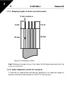
Page 19: ...trip also the plastic cover of the cables for 360 degree grounding See Fig ures 3 4 3 5 and 3 8 3 2 6 Cable installation and the UL standards To meet the UL Underwriters Laboratories regulations a UL approved copper ca ble with a minimum heat resistance of 60 75 0 C must be used 20 mm 35 mm 8 mm Earth conductor 8 mm ...

Page 20: ...n resistance must be 1MOhm 2 Mains cable insulation checks Disconnect the mains cable from terminals L1 L2 N and L3 of the inverter and from the mains Measure the insulation resistance of the mains cable between each phase conductor as well as between each phase conductor and the protective ground con ductor The insulation resistance must be 1MOhm 3 Motor insulation checks Disconnect the motor cab...

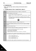
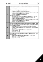
Page 21: ... the quality and quantity of cooling air Chapter 3 1 2 4 Check that all Start Stop switches connected to the I O terminals are in Stop position 5 Connect the inverter to mains 6 Run the Start Up Wizard The Wizard is explained fully in chapter 9 11 1 Activate the wizard by pressing STOP for 5 seconds 2 Tune the motor nominal speed 3 Tune the motor nominal current 4 Select the mode 0 basic 1 Fan 2 P...

Page 22: ...Menu that the value of Output frequency changes according to the change of frequency reference Push the Stop button on the keypad 8 Run the no load tests without the motor being connected to the process if possi ble If this is not possible secure the safety of each test prior to running it Inform your co workers of the tests Switch off the supply voltage and wait up until the drive has stopped Con...

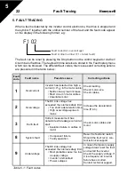
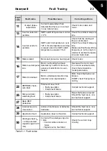
Page 23: ...s Unsuitable motor Check loading Check motor size Check cables 2 Overvoltage The DC link voltage has exceeded the internal safety limit Too short a deceleration time High overvoltage spikes in mains Increase the deceleration time P 4 3 3 Earth fault Current measurement has detected extra leakage current at start Insulation failure in cables or motor Check motor cables and motor 8 System fault Comp...

Page 24: ... Decrease the motor load If no motor overload exists check the temperature model parameters 17 Motor Underload Motor underload protection has detected a low load situation FAN check that belt is not broken PUMP check that pump is not dry 22 EEPROM check sum fault Parameter save fault Faulty operation Component failure Contact technical support 25 Microcontroller watchdog fault Faulty operation Com...

Page 25: ...device 53 Fieldbus fault The data connection between the fieldbus Master and the fieldbus of the drive broken Check installation If installation is correct con tact the nearest Honeywell technical support 57 Identification fault Identification run has failed Run command was removed before completion of identification run Motor is not connected to inverter There is load on motor shaft Fault code Fa...

Page 26: ...mable Special features Programmable Start Stop and Reverse signal logic Reference scaling Programmable start and stop functions DC brake at start and stop Programmable U f curve Adjustable switching frequency Autorestart function after fault Protections and supervisions all fully programmable off warning fault Current signal input fault External fault Undervoltage fault Earth fault Motor thermal s...

Page 27: ...mmunication Modbus 4 AI2 Analog signal in 2 PI actual value P 0 4 20 mA Ri 200 5 GND I O signal ground Ground for reference and controls 13 GND I O signal ground Ground for reference and controls 14 DI4 Digital input 4 Preset speed B1P 0 30V Ri 12 k W minB1 active Preset speed 2 default 15Hz B0 B1 Preset speed 3 default 20 Hz 15 DI5 Digital input 5 Fault reset P 0 30 V Ri 12 k min 16 DI6 Digital i...

Page 28: ... which is printed in clear text on the overlay numbers 1 14 in the figure be low The arrowheads are grouped in 3 groups with the following meanings and Eng lish overlay texts see Figure 7 1 Group 1 5 Drive status 1 Drive is ready to start READY 2 Drive is running RUN 3 Drive has stopped STOP 4 Alarm condition is active ALARM 5 Drive has stopped due to a fault FAULT Group 6 10 Control selections 6 ...

Page 29: ...t it also works as a reference potentiometer when KEYPAD has been selected as the control place of the drive The wheel has two separate func tions Rotating the wheel e g for changing parameter value 12 steps round Pressing the wheel e g for accepting the new value The drive stops always regardless of the selected control place by pressing the key pad STOP button The drive starts by pressing the ke...

Page 30: ... READY RUN MON PUSH FWD REV I O KEYPAD BUS REF PAR FLT FAULT ALARM STOP READY RUN MON FWD REV I O KEYPAD BUS REF PAR FLT FAULT ALARM STOP READY RUN MON PUSH FWD REV I O KEYPAD BUS REF PAR FLT FAULT ALARM STOP READY RUN MON FWD REV I O KEYPAD BUS REF PAR FLT FAULT ALARM STOP READY RUN MON PUSH FWD REV I O KEYPAD BUS REF PAR FLT FAULT ALARM STOP READY RUN MON ROTATE ROTATE ROTATE REFERENCE MENU Disp...

Page 31: ...heel as shown in Figure 7 3 The reference value follows the rotation continuously without separate new value acceptance 7 4 3 Monitoring menu Figure 7 4 Monitoring menu display Hz FAULT ALARM STOP READY RUN REF MON PAR FLT FWD REV I O KEYPAD BUS Push to enter edit mode Change value Push to confirm Hz FAULT ALARM STOP READY RUN REF MON PAR FLT FWD REV I O KEYPAD BUS Alternates in the display Browse...

Page 32: ...red motor current M1 5 Motor torque 4 Calculated actual nominal torque of the motor M1 6 Motor power 5 Calculated actual nominal power of the motor M1 7 Motor voltage V 6 Motor voltage M1 8 DC link voltage V 7 Measured DC link voltage M1 9 Unit temperature C 8 Heat sink temperature M1 10 Motor temperature C Calculated motor temperature M1 11 Analogue input 1 13 AI1 value M1 12 Analogue input 2 14 ...

Page 33: ... 13 1 it is possible to open other advanced parameter groups The parameter lists and descriptions can be found in chapters 8 and 9 The following figure shows the parameter menu view Figure 7 5 Parameter menu Hz FAULT ALARM STOP READY RUN REF MON PAR FLT FWD REV I O KEYPAD BUS Alternates in the display Browse P1 1 Push to enter edit mode Change value Push to confirm ...

Page 34: ...re not pressed or navigation is not rotated The operating hour minute and second values at the fault instant are shown in the value menu operating hours displayed reading x 1000 h Note The whole fault history can be cleared by pressing STOP button for 5 sec time when the drive is stopped and Fault history menu is selected in the diisplay When you are in main menu pressing STOP button will start th...

Page 35: ...de Location indication on the keypad Shows the operator the present Monitoring value number or Parameter number Parameter Name of monitoring value or parameter Min Minimum value of parameter Max Maximum value of parameter Unit Unit of parameter value given if available Default Factory preset value ID ID number of the parameter used with fieldbus control More information on this parameter available...

Page 36: ... terminal 2 Keypad 3 Fieldbus P2 2 Start function 0 1 0 505 0 Ramp 1 Flying start P2 3 Stop function 0 1 0 506 0 Coasting 1 Ramp P3 1 Min frequency 0 00 P3 2 Hz 0 00 101 P3 2 Max frequency P3 1 320 Hz 50 00 102 P3 3 I O reference 0 4 3 117 0 Preset Speeds 0 7 1 Keypad Reference 2 Fieldbus Reference 3 AI1 4 AI2 P3 4 If P3 3 0 Pre set speed 0 0 00 P3 2 Hz 5 00 124 Activated by digital inputs P3 5 Pr...

Page 37: ...urrent 0 20 mA 3 Current 4 20 mA P10 4 Automatic restart 0 1 0 731 0 Not used 1 Used P13 1 Parameter conceal 0 1 1 115 0 All parameters visible 1 Only quick setup parameter group visible Code Parameter Min Max Unit Default ID Note Table 8 1 Quick setup parameters ...

Page 38: ...Nunit 107 P1 8 Motor control mode 0 1 0 600 0 Frequency control 1 Speed control P1 9 U f ratio selection 0 2 0 108 0 Linear 1 Squared 2 Programmable P1 10 Field weakening point 30 00 320 Hz 50 00 602 P1 11 Voltage at field weakening point 10 00 200 100 00 603 of Nominal voltage of the motor P1 12 U f curve midpoint frequency 0 00 P1 10 Hz 50 00 604 P1 13 U f curve midpoint voltage 0 00 P1 11 100 0...

Page 39: ...it Default ID Note P3 1 Min frequency 0 00 P3 2 Hz 0 00 101 P3 2 Max frequency P3 1 320 Hz 50 00 102 P3 3 I O reference 0 4 3 117 0 Preset Speeds 0 7 1 Keypad Reference 2 Fieldbus Reference 3 AI1 4 AI2 P3 4 If P3 3 0 Pre set speed 0 0 00 P3 2 Hz 5 00 124 Activated by digital inputs P3 5 Preset speed 1 0 00 P3 2 Hz 10 00 105 Activated by digital inputs P3 6 Preset speed 2 0 00 P3 2 Hz 15 00 106 Act...

Page 40: ...op 0 00 600 00 s 0 508 0 DC brake is off at stop P4 8 Flux brake 0 3 520 0 Off 2 Chopper 1 On 3 Full mode P4 9 Flux braking current 0 7 4 A 519 P4 10 Ramp shape 2 0 0 10 0 s 0 0 501 0 Linear 0 S curve ramp time P4 11 Acceleration time 2 0 1 3000 s 1 0 502 P4 12 Deceleration time 2 0 1 3000 s 1 0 503 Table 8 5 Motor control parameters Code Parameter Min Max Unit Default ID Note P5 1 Start signal 1 ...

Page 41: ...efault ID Note P6 1 AI1 Signal range 0 3 0 379 0 Voltage 0 10 V 1 Voltage 2 10 V P6 2 AI1 filter time 0 0 10 0 s 0 1 378 0 no filtering P6 3 AI1 Custom min 100 0 100 0 0 0 380 0 0 no min scaling P6 4 AI1 Custom max 100 0 100 0 100 0 381 100 0 no max scaling P6 5 AI2 signal range 2 3 3 390 2 Current 0 20 mA 3 Current 4 20 mA P6 6 AI2 filter time 0 0 10 0 s 0 1 389 0 no filtering P6 7 AI2 Custom min...

Page 42: ...r Active 9 FBControlWord B13 10 FBControlWord B14 11 FBControlWord B15 P7 2 Relay output 2 content 0 8 3 314 As parameter 7 1 P7 3 Digital output 1 content 0 8 1 312 As parameter 7 1 P7 4 Analogue output function 0 4 1 307 0 Not in use 1 Output freq 0 fmax 2 Output current 0 InMotor 3 Torque 0 Nominal torque 4 PI controller output P7 5 Analogue output minimum 0 1 1 310 0 0 mA 1 4 mA P7 6 Relay 2 i...

Page 43: ... 2 2 704 P9 8 Motor ambient temperature 20 100 C 40 705 P9 9 Motor cooling factor at zero speed 0 0 150 0 40 0 706 P9 10 Motor thermal time constant 1 200 min 45 707 P9 11 Motor Phase Supervision 0 2 unit 2 702 0 No response 1 Warning 2 Fault stop mode after fault according to P2 3 Table 8 9 Protections Code Parameter Min Max Unit Default ID Note P10 1 Wait time 0 10 10 00 s 0 50 717 Delay before ...

Page 44: ...ler I time 0 00 320 0 s 10 00 119 P12 4 Keypad PI reference 0 0 100 0 0 0 167 P12 5 Setpoint source 0 3 0 332 0 Keypad PI reference P12 4 1 Fieldbus 2 AI1 3 AI2 P12 6 Feedback source 0 2 2 334 0 Fieldbus 1 AI1 2 AI2 P12 7 Feedback minimum 0 0 100 0 0 0 336 0 No minimum scaling P12 8 Feedback maximum 0 0 100 0 100 0 337 100 0 No maximum scaling P12 9 Error value inversion 0 1 0 340 0 No inversion F...

Page 45: ...ault ID Note Software information MENU PAR S1 S1 1 System SW 2314 S1 2 System SW version 835 S1 3 Power SW ID 2315 S1 4 Power SW version 834 S1 5 Application SW ID 837 S1 6 Application SW revision 838 S1 7 System load 839 RS485 information MENU PAR S2 S2 1 Communication status 808 Format xx yyy xx 0 64 Number of error messages yyy 0 999 Number of correct messages S2 2 Fieldbus protocol 0 1 0 809 0...

Page 46: ...NU PAR S3 S3 1 MWh counter 827 S3 2 Power on days 828 S3 3 Power on hours 829 User settings MENU PAR S4 S4 1 Display contrast 0 15 7 830 Adjusts the display contrast S4 2 Default page 0 20 0 2318 Defines which monitoring page 1 1 1 20 is shown after startup 0 Not used S4 3 Restore factory defaults 0 1 0 831 1 Restores factory defaults for all parameters Code Parameter Min Max Default ID Note Table...

Page 47: ...ION There are three selections for this parameter 0 Linear The voltage of the motor changes linearly with the frequency in the constant flux area from 0 Hz to the field weakening point where the nominal voltage is supplied to the motor Linear U f ratio should be used in constant torque applications See Figure 9 1 This default setting should be used if there is no special need for an other setting ...

Page 48: ...Programmable U f curve 1 10 FIELD WEAKENING POINT The field weakening point is the output frequency at which the output voltage reaches the value set with par 1 11 Un par 1 11 U V f Hz par 1 10 par 1 14 Default Nominal voltage of the motor Linear Squared Field weakening point Default Nominal frequency of the motor Un Par 1 11 Par 1 10 U V f Hz Par 1 13 Def 50 Par 1 14 Def 0 0 Default Nominal volta...

Page 49: ...rogrammable U f curve has been selected with the parameter 1 9 this parameter defines the middle point voltage of the curve See Figure 9 2 1 14 OUTPUT VOLTAGE AT ZERO FREQUENCY This parameter defines the zero frequency voltage of the curve See Figures 9 1 and 9 2 1 15 TORQUE BOOST The voltage to the motor changes automatically with high load torque which makes the motor produce sufficient torque t...

Page 50: ...sed in Run and Stop state When the inverter is decelerating the motor the energy stored to the inertia of the motor and the load are fed into an external brake resistor if the brake chopper has been activated This enables the inverter to decelerate the load with a torque equal to that of acceleration provided that the correct brake re sistor has been selected See separate Brake resistor installati...

Page 51: ...ime P4 2 Load inertia or starting friction may cause prolonged acceleration times 1 Flying start The inverter is able to start also a running motor by applying a small torque to motor and searching for the frequency corresponding to the speed the motor is running at The searching starts from the maximum frequency towards the actual frequency until the correct value is de tected Thereafter the outp...

Page 52: ... able to decelerate the motor in acceptable time 2 4 START STOP LOGIC With this parameter the user can select the start stop logic 0 DI1 Start forward DI2 Start reverse Figure 9 3 Start Stop logic selection 0 1 The first selected direction has the highest priority 2 When the DIN1 contact opens the direction of rotation starts the change 3 If Start forward DI1 and Start reverse DI2 signals are acti...

Page 53: ...eywell 9 1 DI1 Start DI2 Reverse Figure 9 4 Start Stop logic selection 1 2 DI1 Start pulse DI2 Stop pulse Figure 9 5 Start Stop logic selection 2 3 DI1 Start forward rising edge after fault DI2 Start reverse rising edge after fault ...

Page 54: ...reference 2 Reference from Fieldbus FBSpeedReference 3 AI1 reference terminals 2 and 3 e g potentiometer 4 AI2 reference terminal 4 and 5 e g transducer 3 4 3 11 PRESET SPEEDS 0 7 These parameters can be used to determine frequency references that are ap plied when appropriate combinations of digital inputs are activated Preset speeds can be activated from digital inputs despite of the active cont...

Page 55: ...eleration deceleration The acceleration and deceleration times are deter mined with parameters 4 2 and 4 3 Figure 9 6 S shaped acceleration deceleration 4 2 ACCELERATION TIME 4 3 DECELERATION TIME 4 11 ACCELERATION TIME 2 4 12 DECELERATION TIME 2 These limits correspond to the time required for the output frequency to accel erate from the zero frequency to the set maximum frequency or to decelerat...

Page 56: ...nes the time before the brake is released After the brake is released the out put frequency increases according to the set start function by par 2 2 Figure 9 7 DC braking time at start 4 6 FREQUENCY TO START DC BRAKING DURING RAMP STOP The output frequency at which the DC braking is applied See Figure 9 9 t Par 4 5 RUN STOP Output frequency ...

Page 57: ...sing an optional external braking resistor The braking time is scaled by the frequency when the DC braking starts If the frequency is greater than the nominal frequency of the motor the set value of parameter 4 7 determines the braking time When the frequency is 10 of the nominal the braking time is 10 of the set value of parameter 4 7 Figure 9 8 DC braking time when Stop mode Coasting Par 2 3 1 S...

Page 58: ...he motor speed remains controlled during braking Note Flux braking converts the energy into heat at the motor and should be used intermittently to avoid motor damage Activation mode Description 0 Off Not used 1 On Normal mode Activates flux bracking during deceleration regardless of load 2 Chopper Emulates the behavior of a braking chopper by activating flux bracking based on DC link voltage Minim...

Page 59: ...RESET SPEED B1 5 10 PRESET SPEED B2 5 11 DISABLE PI 5 12 FORCE TO I O The control place is forced to I O by activating the digital input that this function is programmed to The priority order of selecting control place is 1 Navigation wheel 2 Forced from I O 3 Parameter 2 1 5 13 RAMP TIME SELECTION Contact open Acceleration Deceleration time 1 selected Contact closed Acceleration Deceleration time...

Page 60: ...RELAY OUTPUT 1 FUNCTION 7 2 RELAY OUTPUT 2 FUNCTION 7 3 DIGITAL OUTPUT 1 FUNCTION Setting Signal content 0 Not used Not in operation 1 Ready The inverter is ready to operate 2 Run The inverter operates motor is running 3 Fault A fault trip has occurred 4 Fault inverted A fault trip has not occurred 5 Alarm An alarm has occurred 6 Reversed The reverse command has been selected 7 At speed The output...

Page 61: ...rive to determine the load on the motor The motor thermal protection can be adjusted with parameters The thermal current IT specifies the load current above which the motor is overloaded This current limit is a function of the output frequency 9 7 THERMAL PROTECTION OF THE MOTOR 0 No response 1 Warning 2 Fault stop mode after fault according to parameter 2 3 If tripping is selected the drive will ...

Page 62: ...RMAL TIME CONSTANT This time can be set between 1 and 200 minutes This is the thermal time constant of the motor The bigger the motor the bigger the time constant The time constant is the time within which the calculated thermal model has reached 63 of its final value The motor thermal time is specific to the motor design and it varies between different motor manufacturers f fn par 9 9 40 0 IT 100...

Page 63: ... increased to three times the set parameter value See also Figure 9 12 Figure 9 12 Motor temperature calculation 9 11 MOTOR PHASE SUPERVISION Motor phase supervision of the motor ensures that the motor phases have an approximately equal current Settings for P9 11 range 0 2 Activation Mode Description 0 No response 1 Warning 2 Fault stop mode after fault according to ID506 P2 3 stop func tion 105 p...

Page 64: ... a fault state is true Figure 9 13 Automatic restart 9 10 PI CONTROL PARAMETERS CONTROL PANEL MENU PAR P12 12 2 PI CONTROLLER GAIN This parameter defines the gain of the PI controller If the value of the param eter is set to 100 a change of 10 in the error value causes the controller output to change by 10 12 3 PI CONTROLLER I TIME This parameter defines the integration time of the PI controller I...

Page 65: ...l 9 12 7 FEEDBACK MINIMUM 12 8 FEEDBACK MAXIMUM Figure 9 14 Feedback minimum and maximum 0V 0mA par 12 7 Custom min par 6 3 6 7 Custom max par 6 4 6 8 par 12 8 10V 20mA Controller feedback Analoque input with custom min and max scaling ...

Page 66: ...lows See the figures below NOTE Running the startup wizard will always return all pa rameter settings to their factory defaults Figure 9 15 Startup wizard FAULT ALARM STOP READY RUN REF MON PAR FLT FAULT ALARM STOP READY RUN REF MON PAR FLT FAULT ALARM STOP READY RUN REF MON PAR FLT rpm Push to enter edit mode Select motor nominal speed and push to confirm Press STOP for 5 seconds in main menu 1 4...

Page 67: ...gure 9 16 Drive setup 9 12 FIELDBUS PARAMETERS CONTROL PANEL MENU PAR S2 The built in Modbus connection of SmartDrive Compact supports the following func tion codes 03 Read Holding Registers 04 Read Input Registers 06 Preset Single Registers ...

Page 68: ... 2104 32104 42104 Motor freq 0 01 Hz 2105 32105 42105 Motor speed 1 Rpm 2106 32106 42106 Motor current 0 01 A 2107 32107 42107 Motor torque 0 1 of nominal 2108 32108 42108 Motor power 0 1 of nominal 2109 32109 42109 Motor voltage 0 1 V 2110 32110 42110 DC voltage 1 V 2111 32111 42111 Active fault Fault code Table 9 3 Output process data ID Modbus register Name Scale Type 2001 32001 42001 FB Contro...

Page 69: ...trol the inverter However you can customise the content of the control word for your own applications because the control word is sent to the inverter as such This is the Reference 1 to the inverter Used normally as Speed reference The al lowed scaling is 0 10000 In the application the value is scaled in percentage of the frequency area between the set minimum and maximum frequencies 15 14 13 12 1...

Page 70: ... Stop Run DIR Clockwise Counter clockwise RST Rising edge of this bit will reset active fault RDY Drive not ready Drive ready FLT No fault Fault active W No warning Warning active AREF Ramping Speed reference reached Z Drive is running at zero speed Table 9 9 Bit definitions ...

Page 71: ...bient tempera ture max 50ºC overload 1 5 x IN max 1min 10min Starting current torque Current 2 x IN for 2 secs in every 20 sec period Torque depends on motor Output frequency 0 320 Hz Frequency resolution 0 01 Hz Control characteristics Control method Frequency Control U f Open Loop Sensorless Vector Control Switching frequency 1 16 kHz Factory default 6 kHz Frequency reference Resolution 0 01 Hz ...

Page 72: ...z Max acceleration amplitude 1 G at 15 8 150 Hz Shock IEC 68 2 27 UPS Drop Test for applicable UPS weights Storage and shipping max 15 G 11 ms in package Enclosure class IP20 EMC Immunity Complies with EN50082 1 2 EN61800 3 Emissions Complies as standard with EN61800 3 category C2 Honeywell level H normal public electricity network requirements Category C1with exter nal EMC filter Honeywell level ...

Page 73: ...ower Nominal input current Mechanical size and weight kg 100 contin current IN A 150 overload current A P kW A COMP230 P25 20 1 7 2 6 0 25 4 2 MI1 0 55 COMP230 P37 20 2 4 3 6 0 37 5 7 MI1 0 55 COMP230 P55 20 2 8 4 2 0 55 6 6 MI1 0 55 COMP230 P75 20 3 7 5 6 0 75 8 3 MI2 0 70 COMP230 1P1 20 4 8 7 2 1 1 11 2 MI2 0 70 COMP230 1P5 20 7 0 10 5 1 5 14 1 MI2 0 70 COMP230 2P2 20 9 6 14 4 2 2 15 8 MI3 0 99 ...

Page 74: ...ability Motor shaft power Nominal input current Mechanical size and weight kg 100 continuous current IN A 150 overload current A 380 480V supply P kW A COMP400 P37 20 1 3 2 0 0 37 2 2 MI1 0 55 COMP400 P55 20 1 9 2 9 0 55 2 8 MI1 0 55 COMP400 P75 20 2 4 3 6 0 75 3 2 MI1 0 55 COMP400 1P1 20 3 3 5 0 1 1 4 0 MI2 0 70 COMP400 1P5 20 4 3 6 5 1 5 5 6 MI2 0 70 COMP400 2P2 20 5 6 8 4 2 2 7 3 MI2 0 70 COMP4...

Page 75: ...cts visit us online at http inverter ecc emea honeywell com Automation and Control Solutions Honeywell GmbH Böblinger Str 17 71101 Schönaich Germany Telephone 49 7031 637 01 Telefax 49 7073 637 493 http inverter ecc emea honeywell com EN1B 0430GE51 R0711 July 2011 2011 Honeywell International Inc ...

Reviews: