Honeywell
Parameter Descriptions 59
9
9.6 ANALOQUE INPUTS (CONTROL PANEL: MENU PAR -> P6)
6.2
AI1
SIGNAL
FILTER
TIME
6.6
AI2
SIGNAL
FILTER
TIME
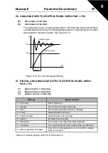
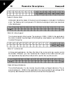
This parameter, given a value greater than 0, activates the function that filters
out disturbances from the incoming analogue signal. Long filtering time makes
the regulation response slower. See Figure 9.10.
Figure 9.10: AI1 and AI2 signal filtering
9.7 DIGITAL AND ANALOQUE OUTPUTS (CONTROL PANEL: MENU
PAR -> P7)
7.1
R
ELAY
OUTPUT
1
FUNCTION
7.2
R
ELAY
OUTPUT
2
FUNCTION
7.3
D
IGITAL
OUTPUT
1
FUNCTION
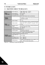
Setting
Signal content
0 = Not used
Not in operation
1 = Ready
The inverter is ready to operate
2 = Run
The inverter operates (motor is running)
3 = Fault
A fault trip has occurred
4 = Fault inverted
A fault trip has not occurred
5 = Alarm
An alarm has occurred
6 = Reversed
The reverse command has been selected
7 = At speed
The output frequency has reached the set reference
8 = Motor regulator activated
One of the limit regulators (e.g. current limit, voltage
limit) is activated
Table 9.2: Output signals via RO1, RO2 and DO1
%
100%
63%
Par. 6.2
Par. 6.6
t [s]
Filtered signal
Unfiltered signal

