


Enhanced Micro TDC 3000 User’s Manual
5-4
9/95
5.1.1
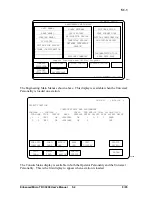
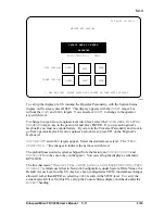
If the Console Status display is on screen, go to subsection 5.1.1.5, Setting the Time and
Date.
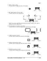
5.1.1.2 How to “Bootload” a US with the Operator Personality from Cartridges
1. If it is not already off, turn off the power switch on tower 1 (the right tower) for a few
seconds and then back on. This resets the nodes in that tower, including US no. 1.
Wait for
>
to appear in the upper left corner of the screen of the monitor connected to
tower 1.
2. Mount the Honeywell-provided cartridge labeled &C2 in drive 1 (the top drive).
3. On the Operator’s Keyboard, press LOAD.
N,1,2,3,4,X
appears.
4. Key in 1, then press ENTER. Several messages appear, ending with
OPR,
UNP
??
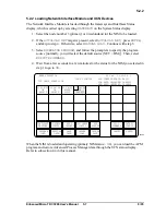
5. Press the ALPHA SHIFT key (until the LED lights), then key in
OPR
and press
ENTER. Several messages appear, ending with NCF?
N,1,2,3,4,X.
6. Mount cartridge &C8 with the prebuilt NCF in drive 2.
7. Key in 2, then press ENTER. This specifies drive 2 as the source of the NCF. After a
few minutes, the message:
AR01? N,1,2,3,4,X?
should appear.
8. Key in 2, then press ENTER. This specifies drive 2 as the source of the Area
Database. After a few minutes, the message:
ABST? N,1,2,3,4,X?
should appear.
9. Key in 2, then press ENTER. This specifies drive 2 as the source of the abstracts.
After a few minutes, the message:
BUTT? N,1,2,3,4,X?
should appear.
10. Key in 2, then press ENTER. This specifies drive 2 as the source of the Configurable
Button file.
11. Wait a few minutes for the Console Status display to appear. If the Console Status
display is on screen, go to subsection 5.1.1.5, Setting the Time and Date.
If the display doesn’t appear within five minutes, something went wrong. Here are some
suggestions for recovery:
•
Try the procedure again.
•
Refer to the Process Operations Manual for information about status conditions that
affect the ability of a US to load.
•
Refer to Section 20 of the Engineer’s Reference Manual. This section has
information about causes of node loading failures, and memory dumps that may be
necessary to analyze such failures.
•
Use the System Startup Guide to start up the Enhanced Micro TDC 3000 System.
Summary of Contents for Enhanced Micro TDC 3000
Page 1: ...L 8 Node Enhanced Micro TDC 3000 User s Manual MT11 520 ...
Page 2: ......
Page 10: ...Enhanced Micro TDC 3000 User s Manual iv 9 95 ...
Page 56: ...Enhanced Micro TDC 3000 User s Manual 3 8 9 95 ...
Page 82: ...Enhanced Micro TDC 3000 User s Manual 4 26 9 95 ...
Page 128: ...Enhanced Micro TDC 3000 User s Manual 5 46 9 95 ...
Page 144: ...Enhanced Micro TDC 3000 User s Manual 6 16 9 95 ...
Page 156: ...Enhanced Micro TDC 3000 User s Manual B 4 9 95 ...
Page 168: ...Enhanced Micro TDC 3000 User s Manual Index 12 7 95 ...
Page 171: ......