


Enhanced Micro TDC 3000 User’s Manual
2-8
9/95
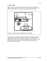
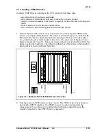
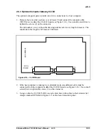
2.7.1
53284
R6
R5
R4
R3
R2
R1
R12
R11
R10
R9
R8
R7
J1
J2
J3
J1
J2
TP485
51304776-100
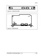
Figure 2-4 — TP485 I/O Board
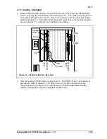
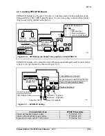
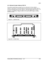
3. The standard cabling connections you will make in the following steps are on the
transition panels in Figure 2-5. Note there are two exposed transition panels—one at
the top of the center section and another at the bottom (see Figure 2-5). The panel has
connectors and cable clamps on it that will be used to secure cables you will install.
Both towers have the same locations for specific connector/clamp brackets but the
bracket types in certain locations may differ depending on the options installed.
53285
Optional PLCG
Relay Panel
Printer
TPLCN
Blank
UCN Taps
Ground (Option)
Options:
PLCG, CG, NG
UCN A & B
Cables (Option)
Keyboard
CRT
CRT
Optional Second
US In Tower
Touchscreen (Option)
Trackball (Option)
Figure 2-5 — Transition Panel Connections—Tower #1 (left) or #2 (right)
4. Note the Optional PLCG Relay Panel in Figure 2-5 above. It can be mounted above the
transition panel, as shown, in the tower containing an optional EPLCG (see Section
2.8.5).
Summary of Contents for Enhanced Micro TDC 3000
Page 1: ...L 8 Node Enhanced Micro TDC 3000 User s Manual MT11 520 ...
Page 2: ......
Page 10: ...Enhanced Micro TDC 3000 User s Manual iv 9 95 ...
Page 56: ...Enhanced Micro TDC 3000 User s Manual 3 8 9 95 ...
Page 82: ...Enhanced Micro TDC 3000 User s Manual 4 26 9 95 ...
Page 128: ...Enhanced Micro TDC 3000 User s Manual 5 46 9 95 ...
Page 144: ...Enhanced Micro TDC 3000 User s Manual 6 16 9 95 ...
Page 156: ...Enhanced Micro TDC 3000 User s Manual B 4 9 95 ...
Page 168: ...Enhanced Micro TDC 3000 User s Manual Index 12 7 95 ...
Page 171: ......