


Enhanced Micro TDC 3000 User’s Manual
2-5
9/95
2.6
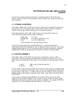
2.6 INSTALLATION
W A R N I N G
DO NOT apply power to any of the Enhanced Micro TDC 3000 Control System equipment
until this installation is completed and this manual tells you to do so. Be sure the power
switches are OFF on all equipment and that no power cords are plugged into electrical ac
mains.
Failure to heed this caution may subject personnel to severe electrical shock or cause
permanent damage to the equipment.
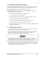
In the following steps, you will move relatively heavy and bulky units containing sensitive
electronic equipment. When moving a tower, we recommend you use two people to place
the tower on a low, flat, roller dolly for transfer within the building. If a hand-truck is
used, it must be well-padded and you must use care not to put excessive stress on the short
feet under the tower.
53282
ASPI-41
Printer
Color Monitor
Engineer's
Keyboard
Operator's Keyboard
Tower #1
Tower #2
25.4 cm
(10")
45.5 cm
(17.9")
Status Indicators
Cartridge Drive (2)
Power Switches
(Table Not Included)
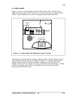
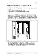
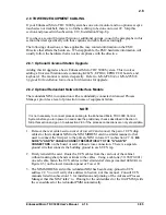
Figure 2-2 — Enhanced Micro TDC 3000 System—Front View
1. First, identify the electronics cabinets. These cabinets (towers) are shown in Figure
2-2 (and in Figure 2-1 with shaded lines). The towers look nearly identical, with a
translucent panel and a power switch near the middle-front of each cabinet. Tower #1
can be identified by two black cartridge drives installed near the top-front of its cabinet.
Tower #1 is also referred to as the “right 4-node” tower; tower #2 as the “left 4-node”
tower.
2. Do not place Color Monitors closer than 12” to each other.
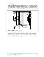
3. Using Figures 2-1 and 2-2 as examples, place the towers in position, parallel to each
other. The printer must be positioned near tower #1 for connection to US #1, but
within the 6 foot length of the printer cable. Put the towers within 84 cm (33") apart
(unless you have the optional 10 meter cable). Make sure both towers sit firmly on
level flooring.
Summary of Contents for Enhanced Micro TDC 3000
Page 1: ...L 8 Node Enhanced Micro TDC 3000 User s Manual MT11 520 ...
Page 2: ......
Page 10: ...Enhanced Micro TDC 3000 User s Manual iv 9 95 ...
Page 56: ...Enhanced Micro TDC 3000 User s Manual 3 8 9 95 ...
Page 82: ...Enhanced Micro TDC 3000 User s Manual 4 26 9 95 ...
Page 128: ...Enhanced Micro TDC 3000 User s Manual 5 46 9 95 ...
Page 144: ...Enhanced Micro TDC 3000 User s Manual 6 16 9 95 ...
Page 156: ...Enhanced Micro TDC 3000 User s Manual B 4 9 95 ...
Page 168: ...Enhanced Micro TDC 3000 User s Manual Index 12 7 95 ...
Page 171: ......