


Enhanced Micro TDC 3000 User’s Manual
3-3
9/95
3.1.2
4. Now initiate power-up tests on tower #1 by setting the
POWER
switch to
ON
. The red
LEDs on the boards light for a few seconds (it takes less than 30 seconds to complete
the power-up tests), then they turn off and the green LEDs turn on. If any red LEDs on
the boards remain on, some portion of the power-up tests have failed—record the
alphanumeric status display code and proceed to Service, Section 6 in this manual.
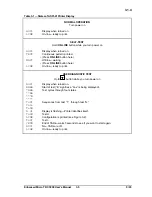
If the power-up test is successfully completed for all nodes, all green LEDs on all
boards are on (there may also be some yellow LEDs on or flashing), and the
alphanumeric status display indicates the node address (ranging from 1 through 8) for
each of the nodes. Temporarily record these three node numbers.
5. Check the power supply status LEDs (
POWER OK
and
ERROR
) and the
FAN ALARM
LED. Note the
FAN ALARM
and
ERROR
LEDs are off and the
POWER OK
LED is on (it
is a fault condition if both the
ERROR
and
POWER OK
LEDs are
ON
).
6. Press the momentary
RESET
switch. Note the power-up tests are initiated similar to
step 4, and the results are satisfactory.
7. Replace the front cover on tower #1 by holding the cover with both hands and catching
the top of the cover into the lip at the top of the cabinet. Be sure the sides of the cover
are on the outside of the cabinet. Now swing the bottom of the cover into place,
pressing firmly on the bottom until the cover is secured by both spring-loaded catches.
3.1.2 Tower #2 Electronics Checks
Tower #2 is similar to tower #1, but it has a 512 MB hard disk drive where the cartridge
drives are located in tower #1 (but the hard disk drive is normally hidden by the front
panel). Note the Multinode Module in tower #2 may not be as completely filled with nodes
as it was in tower #1.
1. Now repeat all the tests in subsection 3.1.1 again on tower #2.
NOTE
Your system has already been shipped with bootload software (Directory & LDR) installed on
the Winchester disk drive. The HM (History Module) automatically boots its node after power-
up tests in this tower have finished.
It is OK to press the RESET switch or turn the power off in the middle of this automatic
bootload because there is no write activity to the drive at this time. However, in an operating
system, NEVER press the RESET switch if there is a possibility of a write-in-process. Please
note the HM automatically boots every other time the RESET switch is pressed.
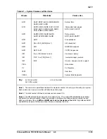
2. Note the node numbers used in tower #2 are different from the node numbers you
found in tower #1. Temporarily record these node numbers. Now compare all of your
node numbers with Table 6-1 in Section 6 of this manual and verify you have the
correct node types.
Summary of Contents for Enhanced Micro TDC 3000
Page 1: ...L 8 Node Enhanced Micro TDC 3000 User s Manual MT11 520 ...
Page 2: ......
Page 10: ...Enhanced Micro TDC 3000 User s Manual iv 9 95 ...
Page 56: ...Enhanced Micro TDC 3000 User s Manual 3 8 9 95 ...
Page 82: ...Enhanced Micro TDC 3000 User s Manual 4 26 9 95 ...
Page 128: ...Enhanced Micro TDC 3000 User s Manual 5 46 9 95 ...
Page 144: ...Enhanced Micro TDC 3000 User s Manual 6 16 9 95 ...
Page 156: ...Enhanced Micro TDC 3000 User s Manual B 4 9 95 ...
Page 168: ...Enhanced Micro TDC 3000 User s Manual Index 12 7 95 ...
Page 171: ......