


Enhanced Micro TDC 3000 User’s Manual
3-1
9/95
3
CHECKOUT
Section 3
This section tells you how to check the Enhanced Micro TDC 3000 Control System after it has
been installed, plugged in and is ready to go.
3.1 POWER-ON TESTS
Do not perform any of these tests until the Enhanced Micro TDC 3000 Control System has
been installed according to Section 2. Check that the rear panels on the towers have been
installed and all signal cables and power cords connected. See that the area is cleared of
packing material and other installation debris, and the area is clean. Check that all power
switches are off.
You will now perform a series of checks and tests to insure the equipment is working. If
any of the tests are not met, refer to Section 6, Service.
3.1.1 Tower #1 Electronics Checks
Tower #1 is the tower on the right with two black cartridge drives in the upper left corner.
1. Use both hands to remove the front panel from tower #1 by grasping the edges of the
panel near the bottom and pulling the panel straight out. Spring-loaded catches on each
side of the panel disengage, and the panel may be removed by pulling it out and down.
Be careful not to damage the cartridge drives when removing the panels.
NOTE
The front panels of the towers may be removed or replaced while power is on because
there are no lethal voltages exposed. Of course, observe caution with metallic objects
because the equipment may still be damaged if low voltages are shorted.
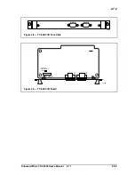
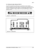
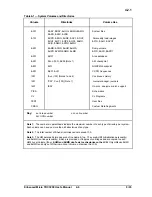
2. You now have access to the front of the Multinode Module in tower #1. Locate the
power switch (see Figure 3-1). Before turning power on, ensure the
LO-NOM-HI
jumper just below and to the right of the power switch is set in the
NOM
or center
position. This is a maintenance jumper that is not to be changed by the user.
3. Compare your module with the Figure 3-1 illustration. Note the module contains four
nodes and each node has a processor board in the first board slot and a personality or
peripheral board in the second slot. Nodes have unique numbers from 1 to 8 (not A,
B, C, D as in the figure) and are factory set. You will identify the node numbers in an
upcoming test. Other board slots may or may-not contain boards, therefore, are shown
shaded. Note a horizontal row of green LEDs along the bottom, with another row of
either yellow or green LEDs just above them. Note each processor board contains a
display containing several red LEDs and a red alphanumeric status display.
Summary of Contents for Enhanced Micro TDC 3000
Page 1: ...L 8 Node Enhanced Micro TDC 3000 User s Manual MT11 520 ...
Page 2: ......
Page 10: ...Enhanced Micro TDC 3000 User s Manual iv 9 95 ...
Page 56: ...Enhanced Micro TDC 3000 User s Manual 3 8 9 95 ...
Page 82: ...Enhanced Micro TDC 3000 User s Manual 4 26 9 95 ...
Page 128: ...Enhanced Micro TDC 3000 User s Manual 5 46 9 95 ...
Page 144: ...Enhanced Micro TDC 3000 User s Manual 6 16 9 95 ...
Page 156: ...Enhanced Micro TDC 3000 User s Manual B 4 9 95 ...
Page 168: ...Enhanced Micro TDC 3000 User s Manual Index 12 7 95 ...
Page 171: ......