


Enhanced Micro TDC 3000 User’s Manual
2-7
9/95
2.7.1
2.7.1 Cabling – Standard
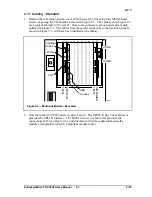
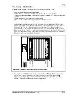
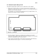
1. Remove the rear center-section cover of both towers by removing four M5 flat-head
screws, exposing the I/O boards as shown in Figure 2-3. The cards seen in Figure 2-3
are a typical example for Tower #1. Note some connectors are not used and are only
outlined in Figure 2-3. The cables from these card connectors to the transition panels,
shown in Figure 2-5, will have been installed at the factory.
53283
7
8
9
10
6
5
4
3
2
1
Printer
CRT
Unused
TP485
EPDGP I/O
TP485
KBD
NIM MODEM
Cartridge
Drives
UCN-A
UCN-B
Figure 2-3 — Multinode Module—Rear View
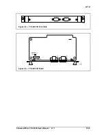
2. Note there are two TP485 cards, in slots 1 and 9. The TP485 in slot 9 of each tower
provides the TPLCN interface. The TP485 in slot 1 in each tower provides the
connection, at J3 (see Figure 2-4), and interface for thermocouples that sense the
module’s temperature (non-EC Compliant modules only).
Summary of Contents for Enhanced Micro TDC 3000
Page 1: ...L 8 Node Enhanced Micro TDC 3000 User s Manual MT11 520 ...
Page 2: ......
Page 10: ...Enhanced Micro TDC 3000 User s Manual iv 9 95 ...
Page 56: ...Enhanced Micro TDC 3000 User s Manual 3 8 9 95 ...
Page 82: ...Enhanced Micro TDC 3000 User s Manual 4 26 9 95 ...
Page 128: ...Enhanced Micro TDC 3000 User s Manual 5 46 9 95 ...
Page 144: ...Enhanced Micro TDC 3000 User s Manual 6 16 9 95 ...
Page 156: ...Enhanced Micro TDC 3000 User s Manual B 4 9 95 ...
Page 168: ...Enhanced Micro TDC 3000 User s Manual Index 12 7 95 ...
Page 171: ......