


Enhanced Micro TDC 3000 User’s Manual
2-16
9/95
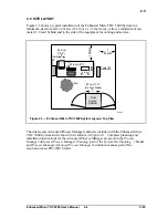
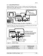
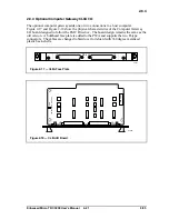
2.7.12
Examine the 15 meter drop cables previously connected to the two UCN taps. Note the
cables are clearly marked "A" and "B."
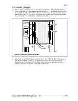
1. Connect these UCN cables to their proper connectors on the lower transition panel (see
Figure 2-5).
BE SURE "A" AND "B" CABLES CONNECT RESPECTIVELY TO THE "A"
AND "B" CONNECTORS
on the panel bracket without cross-connection. If necessary,
check the mini-coax cables from the rear of the panel bracket to the NIM MODEM card
to allow you to confirm the connections.
2. Route the UCN drop cables from the panel out of the cabinet without making sharp
bends or kinks in the cables.
3. Connect a ground wire from the two UCN taps serving this NIM to the screw marked
UCN GND
in Figure 2-5.
4. The NIM MODEM card has been factory-pinned to UCN address #1. You will verify
this address in Section 4 of this manual. Consult UCN manuals listed in subsection
1.5 for installation and pinning of the Advanced Process Manager that this NIM “talks”
to. The PMM in that Advanced Process Manager must be pinned for UCN address #3.
Summary of Contents for Enhanced Micro TDC 3000
Page 1: ...L 8 Node Enhanced Micro TDC 3000 User s Manual MT11 520 ...
Page 2: ......
Page 10: ...Enhanced Micro TDC 3000 User s Manual iv 9 95 ...
Page 56: ...Enhanced Micro TDC 3000 User s Manual 3 8 9 95 ...
Page 82: ...Enhanced Micro TDC 3000 User s Manual 4 26 9 95 ...
Page 128: ...Enhanced Micro TDC 3000 User s Manual 5 46 9 95 ...
Page 144: ...Enhanced Micro TDC 3000 User s Manual 6 16 9 95 ...
Page 156: ...Enhanced Micro TDC 3000 User s Manual B 4 9 95 ...
Page 168: ...Enhanced Micro TDC 3000 User s Manual Index 12 7 95 ...
Page 171: ......