2-14
2.3.5 Level sensor confirmation
- The level sensors of the main ink tank for the PXR-D/PXR-P
and PXR-H are different.
(Refer to the next page for PXR-H)
- The operation confirmation of level sensor in the main ink tank is performed.
(1) Too high
(2) Initial level
- The operation confirmation of level sensor in the ink reservoir is performed.
(1) Too low
- The operation confirmation of level sensor in the makeup ink reservoir is performed.
(1) Too low
- Perform this test in a "stop" or "standby" state.
2.3.5-1 Model PXR-D and PXR-P level sensor confirmation
1 Press adjustment/operational checkout at the second page of the service
maintenance screen.
When the previous menu and the next menu are not displayed in the maintenance menu,
set to the service personnel maintenance mode by the password protection.
2
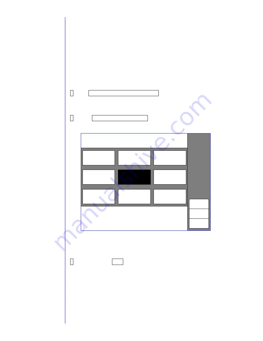
Press Level sensor confirmation.
The level sensor operation state is displayed.
Detected: The sensor detected the level.
(The ink and the makeup ink are present.)
Undetected: The sensor did not detect the level.
(The ink and the makeup ink are not present.)
3
When pressing Back, the screen returns to the adjustment/operational
checkout screen.
With respect to the
password protection,
refer to " 2.1 setting of
service personnel
maintenance mode"
Back
Status:XXXXXXXXX
2011.07.07 12:45
Proc. status: In progress.
<Main ink tank>
Too high [undetected]
Initial
[ detected
]
XXXXXXXXX
XXXXXXXXX
XXXXXXXXX
XXXXXXXXX
XXXXXXXXX
XXXXXXXXX
Level sensor
confirmation
XXXXXXXXX
XXXXXXXXX
<Ink reservoir>
Too low
<Makeup ink reservoir>
Too low
[ detected
] [
detected
]
Adjust./oper. checkout
Summary of Contents for PXR
Page 1: ...Service Manual HITACHI Printer Model PXR Revision December 2008 Version C ...
Page 80: ...3 17 3 17 Circuit diagram of EZJ95 ...
Page 215: ...8 2 8 1 2 Circulation system diagram PXR P ...
Page 216: ...8 2 Air system diagram PXR P 8 3 ...
Page 217: ...8 4 8 3 Electrical Connection Diagram 8 3 1 Electrical Connection Diagram PXR D ...
Page 218: ...8 5 8 3 2 Electrical Connection Diagram PXR H ...
Page 219: ...8 3 3 Electrical connection diagram PXR P 8 6 ...


