ON
OFF
ON
ON
ON
ON
ON
ON
1.ON
2.ON
3.ON
4.ON
1.ON
Depends on the
environment
2.ON
3.ON
1.ON
ON
3.ON
20
30
10
−
Depends on the
environment
Depends on the
environment
ON
1
15
5
5
1
0.5
1
Heating
13
2.ON
Depends on the environ-
ment
15
5
5
1
10
ON
3.ON
3.ON
2.ON
Refresh ink
the MV2
path
12
Pump
ON
ON
ON
ON
ON
ON
ON
1.ON
ON
ON
MV9: Shutoff
5.ON
1.ON
5.ON
1.ON
1.ON
3.ON
1.ON
MV8: Cleaning
1.ON
Heating
MV7: Makeup ink
2.ON
MV6: Pressure relief
1.ON
2.ON
MV5: Circulation
1.ON
2.ON
3.ON
2.ON
2.ON
1.ON
2.ON
1.ON
4.ON
3.ON
3.ON
MV4: Agitation
3.ON
2.ON
MV3: Recovery
2.ON
4.ON
4.ON
4.ON
4.ON
3.ON
1.ON
3.ON
2.ON
1.ON
2.ON
MV2: Replenishment
3.ON
3.ON
MV1: Supply
3.ON
2.ON
1.ON
3.ON
3
3
20
Time [sec.]
PXR-H
Detect the
APH
condition
Ready
(High-
voltage ON)
Ink replenishment
when the ink level
is changed
Makeup Ink
replenishment when the
ink level is changed
Heating
Suck air in
the nozzle
Detect bent
beam
Suck air in
the nozzle
Interval for
stable
pressure
Pressurize
supply path
Suck
circulation
path
Eject
makeup ink
Eject ink
Interval
Pre-heating Refresh ink
in the unit
16
17
15
13
14
8
9
10
11
Remarks
Start sequence
−
1
2
3
4
Operation
ON
Eject Ink
(
Goes to Ready
)
[PXR-H]
[Start up] - [Eject ink]
ON
ON
ON
[Start up] - [Eject ink]
Eject Ink
(
Goes to Ready
)
[PXR-D]
Start sequence
1.ON
3
Refresh ink
in the unit
2.ON
1
4
ON
ON
ON
ON
ON
5
6
7
2.ON
Pressurize
supply path
3.ON
1.ON
ON
ON
ON
2
Interval
Pre-heating
1
Pump
MV4: Agitation
MV5: Circulation
MV6: Pressure relief
MV7: Makeup ink
Sequence Name
Step
Outline
Step
Outline
−
Time [sec.]
MV9: Shutoff
−
Outline
5
Suck
circulation
path
3.ON
2.ON
1.ON
4.ON
2.ON
Eject
makeup ink
3.ON
0.5
1.ON
7
Eject ink
3.ON
4.ON
1
6
4.ON
1.ON
2.ON
5.ON
2.ON
8
Suck air in
the nozzle
3.ON
3
9
Detect bent
beam
3.ON
3
4.ON
2.ON
1.ON
10
Suck air in
the nozzle
3.ON
20
11
2.ON
Interval for
stable
pressure
5
4.ON
1.ON
2.ON
3.ON
1.ON
12
Refresh ink
the MV2
path
30
1.ON
2.ON
2.ON
3.ON
1.ON
3.ON
1.ON
ON
5.ON
30
Detect bent
beam
Suck air in
the nozzle
and stir ink
in the tanks
Interval for
stable
pressure
Refresh ink
the MV2
path
15
16
10
Depends on
the environ-
ment
2.ON
ON
17
1.ON
19
Detect the
APH
condition
Ready
(High-
voltage ON)
18
11
13
14
3.ON
−
ON
1.ON
Sequence Name
Operation
Remarks
14
Ready
(High-
voltage ON)
2.ON
15
Detect the
APH
condition
PXR-D
MV1: Supply
MV2: Replenishment
MV3: Recovery
MV8: Cleaning
Remarks
Step
Sequence Name
Start sequence
Eject Ink
(
Goes to Ready
) [PXR-P]
Interval
Pre-heating Refresh ink
in the unit
and stir ink
in the tanks
Operation
[Start up] - [Eject ink]
12
1
2
3
8
4
9
10
Stop stirrer
Pressurize
supply path
3.ON
4.ON
3.ON
1.ON
6.ON
7.ON
Eject ink
Suck air in
the nozzle
and stir ink
in the tanks
5.ON
20
1.ON
6.ON
Time [sec.]
1
15
PXR-P
5
5
1
0.5
Suck
circulation
path
Eject
makeup ink
1
1.ON
3.ON
3.ON
5
7.ON
20
3
3.ON
2.ON
−
4.ON
3.ON
2.ON
2.ON
1.ON
2.ON
3.ON
3.ON
3
3.ON
4.ON
MV1: Supply
1.ON
2.ON
2.ON
4.ON
MV2: Replenishment
MV3: Recovery
4.ON
2.ON
3.ON
2.ON
3.ON
2.ON
4.ON
4.ON
4.ON
4.ON
2.ON
1.ON
3.ON
MV4: Agitation
3.ON
2.ON
2.ON
1.ON
MV5: Circulation
1.ON
1.ON
6.ON
5.ON
1.ON
2.ON
2.ON
MV6: Pressure relief
1.ON
MV7: Makeup ink
MV8: Cleaning
1.ON
MV9: Shutoff
5.ON
ON
6.ON
1.ON
1.ON
1.ON
3.ON
ON
ON
ON
ON
ON
Pump
ON
ON
ON
ON
ON
ON
ON
ON
ON
ON
ON
ON
MV11: M Stirrer
MV12: S Stirrer
5.ON
Stop stirrer
3
2.ON
5
Stir ink in
the tanks
5
2.ON
6
7
Stir ink in
the tanks
5
2.ON
4.ON
3.ON
1.ON
5.ON
6.ON
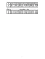
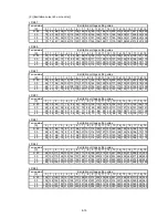
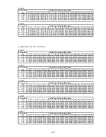
8.4 Circulation sequence
8-7
Summary of Contents for PXR
Page 1: ...Service Manual HITACHI Printer Model PXR Revision December 2008 Version C ...
Page 80: ...3 17 3 17 Circuit diagram of EZJ95 ...
Page 215: ...8 2 8 1 2 Circulation system diagram PXR P ...
Page 216: ...8 2 Air system diagram PXR P 8 3 ...
Page 217: ...8 4 8 3 Electrical Connection Diagram 8 3 1 Electrical Connection Diagram PXR D ...
Page 218: ...8 5 8 3 2 Electrical Connection Diagram PXR H ...
Page 219: ...8 3 3 Electrical connection diagram PXR P 8 6 ...


