background image

4 - 28

Troubleshooting > Trouble Diagnosis

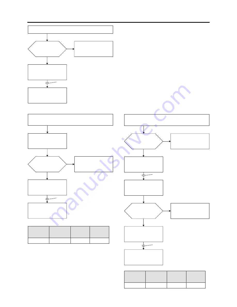
.OIMPROVEMENT

9ES

.O

.OAUDIOFROM!6OUTPUTJACK

.OSOUNDFROM
SPEAKERDURING
PLAYBACKOFVIDEO

2EPLACE*
!6OUTPUTJACK

2EPLACE)

2EPLACETHE-!.CIRCUIT
BOARD

.OIMPROVEMENT

9ES

.O

.OAUDIOCANBERECORDEDFROMINTERNAL
MICROPHONE

3ETTOSERVICEPOSITION!

2EPLACE)

40).4-)#?,

!UDIOSIGNAL

2EPLACE)

2EPLACETHE-!.CIRCUIT
BOARD

,ISTOFCHECKPOINTS

3YMPTOM

#IRCUITBOARD

SIDE 

,OCATIONON

CIRCUITBOARD

,EADWIRE

SOLDERED

ORNOT

%

40

!%,! 

.EEDNOT

.OIMPROVEMENT

.OIMPROVEMENT

9ES

.O

.O

9ES

.OAUDIOCANBERECORDEDFROMEXTERNAL
MICROPHONE

3ETTOSERVICEPOSITION!

2EPLACE11

40%84-)#?,

!UDIOSIGNAL

2EPLACE)

2EPLACETHE-!.CIRCUIT
BOARD

#ANAUDIOFROMTHE
INTERNALMICROPHONE
BERECORDED

2EFERTO.OAUDIOCANBE
RECORDEDFROMINTERNAL
MICROPHONE

#HECKTOSEEWHETHERA
PLUGINPOWERTYPE
MICROPHONEISBEING
USED

,ISTOFCHECKPOINTS

3YMPTOM

#IRCUITBOARD

SIDE 

,OCATIONON

CIRCUITBOARD

,EADWIRE

SOLDERED

ORNOT

%

40

!%,! 

.EEDNOT

Summary of Contents for DZ-BD70A - Camcorder

Page 1: ...CE MANUAL SPECIFICATIONS AND PARTS ARE SUBJECT TO CHANGE FOR IMPROVEMENT YBRID AMCORDER AMCORDER HYBRID BD CAMCORDER BD CAMCORDER TK No 0706E DZ BD7HA DZ BD70A DO NOT RESELL OR DIVERT IMPROPERLY October 2007 ...

Page 2: ...odes and troubleshooting 4 13 4 3 4 BD DVD Load Check Flowchart 4 15 4 3 5 Cleaning BD DVD and optical pickup 4 16 4 4 Checking Versions of Firmware and Updating 4 17 4 4 1 Checking firmware versions 4 18 4 4 2 Updating firmware 4 18 4 5 Trouble Diagnosis 4 20 4 5 1 Trouble diagnosis flowchart 4 21 4 5 2 Reassembly to enable service position 4 33 4 6 Procedure for Removing BD DVD from Faulty Camco...

Page 3: ... 5 S 6 CAMERA µP MAN S 6 S 7 CODEC MAN S 7 S 8 MEMORY MAN S 8 S 9 I O MAN S 9 S 10 HDMI MAN S 10 S 11 USB IC MAN S 11 S 12 HDD MAN S 12 S 13 REGULATOR MAN S 13 S 14 PLUG MAN S 14 S 15 USB S 15 S 16 AEL S 16 S 17 LAF S 17 S 18 EXL S 18 S 19 FRT S 19 S 20 AVS S 20 S 21 SFF S 20 S 22 MIC S 21 S 23 IC Block 1 2 S 22 S 24 IC Block 2 2 S 23 C Circuit Board Diagrams C 1 C 1 5MCMOS C 1 C 2 AEL C 2 C 3 EXL...

Page 4: ... the current HITACHI Service Manual A subscription to or additional copies for HITACHI Service Manual may be obtained at a nominal charge from HITACHI SALES CORPORATION PRODUCT SAFETY NOTICE CAUTION There is a high voltage section inside the camcorder When repairing or inspecting it take great care to prevent electric shock Use an isolating transformer wear gloves etc Lithium battery danger of exp...

Page 5: ...optical pickups to any severe vibrations or impact during movement installation or disassembly 2 When performing repair work do not perform disassembly any further than that described in this manual 3 Never turn the semi variable resistors for adjustment in optical pickup or BD or DVD drive 4 NEVER look into the objective lens in optical pickup or directly view the laser light You could lose your ...

Page 6: ...harger during recording playback editing or dubbing Doing so could damage the data on HDD Always set the power switch to OFF before removing the power supply 2 Do not subject the camcorder to any vibration as far as possible during recording playback editing or dubbing Also never strike the camcorder The head will hit the disk which could damage the HDD 3 Caution during repacking 1 Use the packing...

Page 7: ...e following before soldering Caution ALWAYS wear protective goggles during soldering so that no solder smoke or scattered solder enters the eye Lead free solder may scatter at high temperatures of 600 C 1 Identification of circuit boards that use lead free solder is stamped or noted with pattern letter on circuit boards that use lead free solder 2 Characteristics of lead free solder The components...

Page 8: ... 1 Before using lead based solder remove the lead free solder completely from the point to be soldered 2 For additional soldering for repair set the soldering iron tip temperature for lead free solder mix lead based solder and lead free solder sufficiently Do not perform any repair using the bare soldering iron tip without adding solder since it will cause secondary failure due to lack of strength...

Page 9: ...des A B in circuit board diagrams 1 Board with pattern on one side only and parts on both sides Side A Shows discrete parts Side B Shows leadless parts viewed from the pattern side 2 Board with patterns and parts on both sides Sides A and B are identified without any predetermined rules Parts Indication in list Regular indication Resistor KOHM k Capacitor UF μF PF pF Coil UH μH MH mH Item Indicati...

Page 10: ...D875LA D975LA D875LA 2 If there is no difference in models going to different destinations the indication of destination is omitted Example When indicating DZ MV350E AU and DZ MV350E SW DZ MV350E 5 Differences in parts between schematic and circuit board diagrams If some parts are different between models asterisks are attached to the circuit numbers Check the parts difference tables in diagrams o...

Page 11: ...BD7HA and DZ BD70A can record High Definition HD images on a Blu ray disc BD The DZ BD7HA also has a 30 GB HDD 1 8 inch and so it can record high definition HD images on the HDD Since the DZ BD7HA and DZ BD70A are compatible with various discs as shown in Table 2 1 1 it can record movies directly to a disc or the HDD and also easily dub movies recorded on the HDD to a disc dubbing from a disc to H...

Page 12: ...placement m MAN circuit board Component replacement or circuit board replace ment n AEL circuit board Component replacement o USB circuit board Component replacement p LAF circuit board Component replacement q AVS circuit board Component replacement r EXL circuit board Component replacement Table 2 1 2 Servicing method Fig 2 1 1 Name of the circuit board unit 2 1 1 Servicing method Refer to the fo...

Page 13: ...on another model be played back General Description Features Specifications 2 3 Specifications Item Specifications Image Sensor 1 2 8 inch CMOS sensor Total number of pixels Approx 5 300 000 Number of effective pixels Movie Approx 2 070 000 Still Approx 4 320 000 Lens F1 8 3 0 f 3 16 1 15 16 5 50mm Filter diameter Thread pitch 1 11 16 43mm 0 75mm Focus Auto Manual Zoom Optical 10 40 500 with digit...

Page 14: ...ovie BD RE Ver 3 0 Sound Dolby Digital BD R Movie BD R Ver 2 0 Sound Dolby Digital DVD RAM DVD RW VR mode Movie Conforming to DVD video recording DVD VR format Sound Dolby Digital DVD RW VF mode DVD R Movie Conforming to DVD video format Sound Dolby Digital Card Still JPEG standard 2400 1800 pixels When capturing still images 1920 1080 pixels HDD BD 640 360 pixels DVD Audio playback format Dolby D...

Page 15: ...lative humidity 20 80 Item Specifications Allowable operating altitude when using HDD DZ BD7HA only 9 842 feet 3 000 m or less Weight without battery pack nor BD DVD DZ BD7HA Approx 630g DZ BD70A Approx 575g Total weight when recording When using the battery pack DZ BP14S DZ BD7HA Approx 705g DZ BD70A Approx 650g Provided accessories AC adapter charger DZ ACS3 Battery DZ BP14S AV S output cable Co...

Page 16: ... playback Possible usable media HDD BD RE BD R Impossible Image sensor 1 2 8 inch CMOS sensor 1 6 inch CCD sensor Total number of pixels Approx 5 300 000 pixels Approx 680 000 pixels Number of pixels for Movie Approx 2 070 000 pixels Approx 340 000 pixels Number of pixels for still Approx 4 320 000 pixels Approx 340 000 pixels Lens F1 8 3 0 f 3 16 1 15 16 5 50 mm F2 0 4 1 f 1 16 2 11 16 2 3 69 mm ...

Page 17: ...els HF HS 1 1440 1 080 pixels SX SF 1 720 480 pixels XTRA FINE 720 480 pixels STD 352 480 pixels Audio recording format Dolby Digital Audio playback format Dolby Digital MPEG Audio layer 2 Linear PCM LPCM Maximum number of record able Stills 32MB SD memory card used Approx 10 FINE Approx 180 NORM Approx 240 ECO Approx 370 Number of pixels for JPEG Still during camera recording 2 400 1 800 pixels 4...

Page 18: ...BD7HA and DZ HS500A Provided Accessory Shoe Provided Not provided AV S input output jack Provided output only DZ HS500A Provided Except for S input DZ GX5080A Provided output only External microphone jack Provided a plug in power type micro phone only Not provided PC connection terminal USB standard Type mini B USB 2 0 HDD Read only HDMI terminal Provided Not provided Component output terminal Pro...

Page 19: ...s 1 DVD RAM 1 DVD RAM recorded or edited on DZ BD7HA BD70A The DVD RAM can be recorded edited and played 1 on other Hitachi Hybrid BD DVD camcord ers 2 DVD RAM recorded or edited on other Hitachi Hybrid BD DVD camcorders The DVD RAM can be recorded edited and played 1 on DZ BD7HA BD70A However scene memos recorded on the Disc Navigation function of DZ MV100A cannot be played or edited on another m...

Page 20: ...VD cam corders 5 2 DVD RW VR recorded or edited on other Hitachi Hybrid BD DVD camcorders 5 The DVD RW VR can be recorded edited and played back on DZ BD7HA BD70A in the same way 5 Only for models that conform to DVD RW See Table 2 5 1 List of Compatible Recording Media for the models that conform 4 DVD RW VF mode 1 DVD RW VF recorded or edited on DZ BD7HA BD70A The DVD RW VF can be played back on...

Page 21: ... No SD Rp ST No No HD No SD No ST Rp No DZ BD70A No DZ HS500A HD No SD Rp ST No No HD No SD Rp ST No DZ HS303A DZ HS300A DZ GX5080A DZ GX5020A DZ GX5000A No HD No SD Rp ST Rp DZ GX3300A DZ GX3200A DZ GX3100A DZ BX37A DZ BX35A DZ GX20MA DZ MV780MA DZ MV750MA DZ BX31A No DZ GX20A DZ MV780A DZ MV730A No DZ MV580A 2 DZ MV550A 2 HD No SD No ST Rp DZ MV380A 2 DZ MV350A 2 DZ MV270A 1 DZ MV230A 1 DZ MV200...

Page 22: ...ITCH OCK BUTTON AND STRAP 6 COMPARTMENT JACK 30 9 BUTTON BUTTON 3PEAKER 80 352 BUTTON 5 BUTTON 4HIS BUTTON CAN HELP YOU CHOOSE A DISC CONNECT THE CAMCORDER TO YOUR 46 AND SO ON 4HE SECTIONS IN THE NSTRUCTION ANUAL FOR WHICH THIS BUTTON CAN BE USED ARE INDICATED BY A POP UP ICON LIKE THE ONE BELOW 5 54 BUTTON 5SE THE 5 BUTTON FOR HELP 2 3 4 BUTTON 15 34 24 BUTTON 3 6 4 BUTTON 5 BUTTON 0 CONNECTION ...

Page 23: ... SENSOR 5SED TO CONTROL FLASH AMOUNT O NOT BLOCK THE LIGHT RECEIVING SENSOR WITH YOUR HAND WHEN RECORDING STILL PICTURES 2ECORDING INDICATOR 2EMOTE CONTROL RECEIVER NFRARED SENSOR 0 4 OUTPUT TERMINAL 6 54 TERMINAL MONITOR COLOR WIDE SCREEN 0 4 2 30 9 4 5 3 4 4 3 6 4 0 4 BUTTON 2 BUTTON 5 BUTTON 3 4 BUTTON REVERSESEARCH BUTTON 4 BUTTON 3 6 4 BUTTON 30 9 BUTTON 4 BUTTON 4 BUTTON 7 BUTTON REVERSE SKI...

Page 24: ...TE CONTROL 7 2 EEP THIS BATTERY AWAY FROM CHILDREN F SWALLOWED CONSULT A PHYSICIAN IMMEDIATELY FOR EMERGENCY TREATMENT 0OWER CABLE ONNECTS THE ADAPTER CHARGER TO THE OUTLET 6 3 CABLE 5SE THIS CABLE TO VIEW IMAGES FROM THE CAMCORDER ON A 46 R OUTPUT THE IMAGES AND SOUND TO ANOTHER VIDEO RECORDING DEVICE OMPONENT CABLE 5SE THIS CABLE WHEN A COMPONENT TERMINAL IS EQUIPPEDON YOUR 46 5SETHE 6 3 CABLE F...

Page 25: ...tem This is the copy control technology used by video devices Referred to as CGMS A for analog technology and CGMS D for digital technology Component terminal Application standard for analog video signal input output terminals which transfer the video signal by dividing it into luminance and color difference cr cb and sync signals CPRM Content Protection for Recordable Media A copyright protection...

Page 26: ...ly recognizes noise that randomly occurs between frames and removes it Full HD See HDTV HD H HD DVD One type of DVD to and from which data is written and read using blue violet laser The DVD Forum is establishing promulgating and promoting the format specifica tions HDMI Digital video audio input output interface standard for consumer electronics and AV devices A single HDMI cable allows sending a...

Page 27: ...ion Television Conventional TV format These terms are used when comparing with HDTV HD SD Memory Card Formally named Secure Digital Memory Card This compact memory card 32 mm long 24 mm wide 2 1 mm thick is equipped with an advanced copyright protection function SecureMMC See Secure MultiMediaCard Secure MultiMe diaCard Also referred to as SecureMMC This compact memory card has multimedia card spe...

Page 28: ...a BD drive unit b EVF unit c Flash unit d HDD unit DZ BD7HA only e LCD unit f Lens unit g 5MCMOS circuit board Relays the CMOS image sensor to the MAN circuit board On the parts list this circuit board is registered as Sensor Assy and a CMOS image sensor is mounted on the board h AEL circuit board Supplies the analog video audio signals etc to EVF unit LCD unit and various output terminals etc Thi...

Page 29: ...t board DZ BD7HA only This file like board connects the HDD unit and MAN circuit board n LAF circuit board Connects the AEL and EXL circuit boards o MAN circuit board Incorporates the entire Hybrid BD camcorder control circuit video audio signal processing circuit power supply circuit etc p MIC circuit board Incorporates the amp circuit of built in microphone q SFF circuit board Connects the FRT c...

Page 30: ... Blu ray disc file system This recording format will improve the playback response The BD FS format divides the disc recording area between real time data area where the stream of video audio etc is recorded and the gathered file area where the stream control database is recorded which improves the response Table 3 2 1 Comparison of Specifications between BD and DVD Item BD single sided 1 layer DV...

Page 31: ...2 0 Format corresponding to the DVD Video format in DVD formats Recording playback possible BDAV BD AV Format corresponding to the DVD Video Recording format in DVD formats Incompatible Table 3 2 4 Formats of Audio Recording Playback on BD Format Compatibility with DZ BD7HA BD70A Remarks Dolby Digital Recording playback possible dts DTS Incompatible Linear PCM Only playback possible Dolby Digital ...

Page 32: ... Operation Description of Newly Adapted Technology Signal Recording playback format Video Movie Equivalent BD RE Ver 3 0 Photo Cannot be recorded Audio Dolby Digital Table 3 2 6 HDD Recording Playback Format Table 3 2 7 High Definition Video Formats Format 1080i 1080p 720p Resolution 1920 1080 1440 1080 1920 1080 1440 1080 1280 720 960 720 Scanning system Interlaced Progressive Progressive Number ...

Page 33: ...of Newly Adapted Technology Item CMOS sensor CCD sensor Smears when a subject with vehicle headlight etc is shot a vertical light band will occur above and below the light source Does not occur Occurs Output signal Digital 6 Analog Focusing rapidly moving subject Not good Good Pixel data readout speed Speedup is possible Suitable for greater increases in pixel numbers Speedup is limited Not suitab...

Page 34: ... Take notes of settings on received product in the Memo columns referring to Table 4 7 1 List of items to be reset These notes will be necessary not only for reset but for checking any defects that occur under the particular setting conditions Troubleshooting 1 Messages and error codes will appear on LCD monitor or in viewfinder Fig 4 1 1 HECK PHENOMENON O MESSAGE APPEARS ESSAGE APPEARS ISPLAY OF ...

Page 35: ...eate a play list first and then combine on the playlist Cannot combine Select multiple scenes Appears when combining one scene was attempted Select multiple scenes and then com bine them Cannot delete scene Delete other scenes first and then retry Appears if an attempt is made to delete a divided scene when the number of scenes has reached the registrable limit Refer to 1 and 3 on page 4 11 To del...

Page 36: ...ding Prepare another card or delete unnecessary stills Card error has occurred Appears when the card cannot be recognized because its terminals are dirty Use a dry cloth to clean the card terminals Also appears when data other than photos is recorded on card Replace the card Card error has occurred Format the card now YES NO Appears when a card initialized on PC etc or a card whose initialization ...

Page 37: ...ormation Start Disc Navigation press the MENU button and then execute Update Control Info in the BD DVD Set ting menu Disc almost full Appears when the movie recordable capacity on the BD DVD is less than one minute Delete unnecessary scenes Or replace the BD DVD Disc error has occurred Also appears when reading or writing from to recorded file cannot be per formed be cause the BD DVD is dirty Ref...

Page 38: ...reconnect it and turn the power switch to the BD DVD mode The camcorder will automatically repair movie file Disc error has occurred Turn the power switch off once and then set it to BD DVD Appears when BD DVD error occurred during dubbing and a file could not be written Turn the power switch to OFF Disconnect the AC adapter charger and then reconnect it and turn the power switch to the BD DVD mod...

Page 39: ... VR Mode VF Mode and designate it Appears when reading or writing from to recorded file cannot be performed be cause the DVD RAM is dirty Refer to 4 3 5 Cleaning BD DVD and optical pickup and clean the BD DVD Or replace the BD DVD May appear when a BD DVD format ted and recorded on a device other than camcorders is loaded Use a PC etc to check the contents on BD DVD Appears when an unformatted BD ...

Page 40: ...e YES and designate it to finalize the BD DVD Found damaged video Re cover video data YES NO Appears when reading writing of recorded files cannot be performed because the BD DVD is dirty If the message appears immediately after recognition of a loaded recorded disc was finished first check for dirt on BD DVD Refer to 4 3 5 Cleaning BD DVD and optical pickup and clean the BD DVD Or replace the BD ...

Page 41: ...protected by a de vice other than the DZ BD7HA BD70A This occurs because the HDD protection function equipped with DZ BD7HA BD70A protects the entire HDD it does not handle protection of individual pro grams scenes Release the protection using the device on which the programs scenes were protected or choose YES and then delete the scenes HDD is full Cannot add control info Appears if the number of...

Page 42: ... operation if even one play list has been created during scene deletion This mes sage does not appear when a scene is deleted from play list Choose YES and designate it to delete selected scenes Scene is too short Cannot divide Appears if an attempt is made to divide an very short scene If division of scenes is repeated an extremely short scene may be generated Give up the division of scene Scene ...

Page 43: ...it until the message disappears This disc is recorded by the PAL system Please replace disc Appears when a disc recorded in the PAL system was loaded This camcorder is exclusively for the NTSC system and does not comply with the PAL system Use a disc recorded in the NTSC system Unformat disc Appears when an unformatted or logically damaged BD DVD was loaded Format the BD DVD deleting all re corded...

Page 44: ...sing a battery connected limited to a battery with remaining power level more than the half The specifications state that repairing video files on BD DVD can be executed only when the AC adapter charger is connected d Although repair is normally finished in several minutes it could take approx one hour e If the BD DVD is removed while it is being recognized the repair function of movie file will b...

Page 45: ...tton operation Simultaneously press the QUICK START REC buttons and joystick 2 Display clearing method 1 Press the STOP EXIT button to restore the thumbnail screen Troubleshooting Display of Error Codes and Troubleshooting Fig 4 3 1 Example of Error Code Display RROR ODE 2 452 ODE ATE4IME INUTES OUR AY ONTH 0ROBLEM OCCURRENCE DATE TIME RROR CODE 4 3 2 Details of error code display Up to four error...

Page 46: ...cessed Any vibration or impact to BD DVD while it is being ac cessed will result in no recording 5122 Movie or still file cannot be opened Clean the BD DVD and optical pickup referring to 4 3 5 Cleaning BD DVD and optical pickup Replace the BD DVD Replace the BD drive unit 7601 Optical pickup was faulty Replace the BD drive unit 77xx 2 Formatting BD DVD failed Clean the BD DVD and optical pickup r...

Page 47: ...et during initialization 2 This means an error in 7700s Numerals will appear in digits xx for actual error codes Error code Contents of problem Troubleshooting F572 Recording Movies failed due to mag netic substance in the vicinity of opti cal pickup Remove the magnetic substance taking care that the optical pickup is not damaged F573 F700 BD drive unit was faulty Replace the BD drive unit FB00 Op...

Page 48: ...Fig 4 3 2 BD DVD Load Check Flowchart O 9ES 9ES O O 9ES O 9ES O 9ES O 9ES O 9ES HECK THE 6 LOADED STATUS S A SINGLE SIDED 6 USED S 6 LOADED WITH THE RECORDING SURFACE FACING THE OPTICAL PICKUP OAD THE 6 WITH THE RECORDING SURFACE FACING THE OPTICAL PICKUP S 6 PROPERLY ATTACHED TO THE TURNTABLE 0USH THE 6 ONTO THE TURNTABLE UNTIL A CLICK IS HEARD S THERE A FOREIGN OBJECT IN THE VICINITY OF TURNTABL...

Page 49: ...so usable a KS2424 X00 Toraysee cleaning cloth only produced by Toray b LF K200DCJ1 DVD RAM PD disc cleaner cleaning cloth and cleaning liquid produced by Panasonic c DVD 8CL S 8cm DVD video camera lens cleaner cleaning disc and cleaning cloth produced by Hitachi Maxell 2 Cleaning optical pickup Note Do not clean the optical pickup needlessly The optical pickup is a precision component Repeated cl...

Page 50: ...al Pickup 4 4 Checking Versions of Firmware and Updating The camcorder stores in flash memory the nine types of firmware program shown in Table 4 4 1 Information 1 The information on how to upgrade the firmware obtain firmware data and create a disc or card containing upgraded firmware will be reported on service bulletin etc 2 Updating the firmware may improve a malfunction of product Check the v...

Page 51: ...for updating a model other than that to be serviced is inserted an mismatch screen will appear Stop updating and remove the DVD RAM SD memory card 1 Acquire the data for updating of firmware and create a DVD RAM or SD memory card for updat ing Information on how to do this will be reported on service bulletin etc 2 Set the power switch to OFF and then use the AC adapter charger to power the camcor...

Page 52: ...e stored in camcorder the same version screen will appear 6 When all required updating is complete the screen for verifying the version of updated firmware will appear and the updated firmware will be displayed in red Make sure that the firmware has been updated to agree with the details specified by the technical bulletin etc 7 To complete updating set the power switch to OFF and then remove the ...

Page 53: ...ally HDD system For DZ BD7HA HDD does not operate Message HDD access does not disappear Disc system Recognition of BD DVD does not start even if a normal BD DVD is loaded Message No disc appears even if a normal BD DVD is loaded Message Disc access does not disappear even if a normal BD DVD is loaded Message Write protected Check disc appears even if a BD DVD with no write protect is loaded Messag...

Page 54: ...S O 9ES O O 9ES 9ES O 9ES O 9ES O 9ES O 0OWER DOES NOT TURN ON OR START UP NORMALLY 40 PPROX 6 2EPLACE 1 OR 1 40 PPROX 6 2EPLACE IST OF CHECK POINTS 3YMPTOM IRCUIT BOARD SIDE OCATION ON CIRCUIT BOARD EAD WIRE SOLDERED OR NOT EED NOT EED NOT 40 EED NOT EED NOT EED NOT EED NOT EED NOT RE ANY OF FUSES BLOWN OVIE 3TILL SWITCH FAULTY 2EPLACE THE REAR CASE 3ET THE OVIE 3TILL SWITCH TO h OVIEv POSITION A...

Page 55: ...NIT AND S FUSE BLOWN 2EPLACE THE CIRCUIT BOARD FTER REPLACING THE FUSE SUPPLY POWER WITH NO 3 92 OR CIRCUIT BOARD CONNECTED 2EPLACE THE 3ENSOR SSEMBLY S FUSE BLOWN FTER REPLACING THE FUSE SUPPLY POWER WITH 3 CIRCUIT BOARD CONNECTED O 92 OR CIRCUIT BOARD CONNECTED 4HE SENSOR ASSEMBLY COMPRISES THE 3 BOARD ON WHICH A 3 SENSOR IS MOUNTED FTER REPLACING THE FUSE SUPPLY POWER WITH 92 AND 3 CIRCUIT BOAR...

Page 56: ...OSED 3ET TO SERVICE POSITION OES THE VOLTAGE AT 40 6 0 VARY OCK UNIT FAULY 2EPLACE THE 2 CASE 2EPLACE THE CIRCUIT BOARD IST OF CHECK POINTS 3YMPTOM IRCUIT BOARD SIDE OCATION ON CIRCUIT BOARD EAD WIRE SOLDERED OR NOT 40 EED 2EMOVE THE CIRCUIT BOARD AND SOLDER A LEAD WIRE TO CHECK POINTS Information With the DZ BD7HA the HDD unit is set to master and the BD drive unit is set to slave Therefore if th...

Page 57: ...OARD SIDE OCATION ON CIRCUIT BOARD EAD WIRE SOLDERED OR NOT 40 EED 2EMOVE THE CIRCUIT BOARD AND SOLDER A LEAD WIRE TO CHECK POINTS OCK UNIT FAULY 2EPLACE THE 2 CASE ESSAGE ISC ACCESS DOES NOT DISAPPEAR EVEN IF A NORMAL 6 IS LOADED 2EPLACE THE DRIVE UNIT ESSAGE 7RITE PROTECTED HECK DISC APPEARS EVEN IF A 6 WITH NO WRITE PROTECT IS LOADED 2EPLACE THE DRIVE UNIT ESSAGE ISC IS NOT FORMATTED ORMAT THE ...

Page 58: ...CK 40 40 6IDEO SIGNAL 2EPLACE THE UNIT 2EMOVE THE CIRCUIT BOARD AND SOLDER A LEAD WIRE TO CHECK POINTS 3ET TO SERVICE POSITION OES BACKLIGHT TURN ON 2EPLACE THE UNIT 2EPLACE THE CIRCUIT BOARD 40 40 40 6 6 40 40 8 IST OF CHECK POINTS 3YMPTOM IRCUIT BOARD SIDE OCATION ON CIRCUIT BOARD EAD WIRE SOLDERED OR NOT EED 40 8 EED NOT EED 2EPLACE THE CIRCUIT BOARD 2EPLACE THE CIRCUIT BOARD 40 EED 40 EED ...

Page 59: ...E OR PLAYBACK IMAGE OUTPUT 2EPLACE THE CIRCUIT BOARD OES IMAGE APPEAR IN VIEWFINDER OR ON MONITOR S PLAYBACK IMAGE OUTPUT 2EFER TO AMERA RECORDED IMAGE IS ABNORMAL 2EPLACE THE CIRCUIT BOARD O VIDEO SIGNAL FROM 6 OUTPUT JACK 40 6 6IDEO SIGNAL 2EPLACE THE 6 OUTPUT 2EMOVE THE CIRCUIT BOARD AND SOLDER A LEAD WIRE TO CHECK POINTS 3ET TO SERVICE POSITION 2EPLACE THE CIRCUIT BOARD 9 54 UMINANCE SIGNAL 2E...

Page 60: ...EAD WIRE TO CHECK POINTS IST OF CHECK POINTS 3YMPTOM IRCUIT BOARD SIDE OCATION ON CIRCUIT BOARD EAD WIRE SOLDERED OR NOT EED EED 40 40 40 40 EED EED 40 6 PPROX 6 40 6 6 40 39 40 639 0ULSES 2EPLACE 1 AND 1 2EPLACE THE CIRCUIT BOARD AMERA RECORDED IMAGE IS ABNORMAL 2EPLACE 1 AND 1 2EPLACE THE CIRCUIT BOARD 2EPLACE THE 3ENSOR SSEMBLY 4HE SENSOR ASSEMBLY COMPRISES THE 3 BOARD ON WHICH A 3 SENSOR IS MO...

Page 61: ...K POINTS 3YMPTOM IRCUIT BOARD SIDE OCATION ON CIRCUIT BOARD EAD WIRE SOLDERED OR NOT 40 EED NOT O IMPROVEMENT O IMPROVEMENT 9ES O O 9ES O AUDIO CAN BE RECORDED FROM EXTERNAL MICROPHONE 3ET TO SERVICE POSITION 2EPLACE 1 1 40 84 UDIO SIGNAL 2EPLACE 2EPLACE THE CIRCUIT BOARD AN AUDIO FROM THE INTERNAL MICROPHONE BE RECORDED 2EFER TO O AUDIO CAN BE RECORDED FROM INTERNAL MICROPHONE HECK TO SEE WHETHER...

Page 62: ...UTPUT JACK 2EFER TO O AUDIO SIGNAL FROM 6 OUTPUT JACK 2EMOVE THE CIRCUIT BOARD AND SOLDER A LEAD WIRE TO CHECK POINTS 3ET TO SERVICE POSITION 3PERKER FAULTY 2EPLACE THE CASE 40 40 30 54 UDIO SIGNAL 40 8 40 IST OF CHECK POINTS 3YMPTOM IRCUIT BOARD SIDE OCATION ON CIRCUIT BOARD EAD WIRE SOLDERED OR NOT EED EED NOT 2EPLACE 2EPLACE THE CIRCUIT BOARD ...

Page 63: ... LEAD WIRE TO CHECK POINTS O 9ES O 9ES O 9ES O 9ES 0 4 BUTTON FOCUS LOCK DOES NOT FUNCTION 40 53 6 7HEN 0 4 BUTTON IS PRESSED ALL THE WAY 3ET TO SERVICE POSITION OES AUTOFOCUS OPERATE 2EFER TO UTOFOCUS DOES NOT OPERATE OES FOCUS LOCK WHEN 0 4 BUTTON IS PRESSED HALFWAY 40 3 544 2 6 0 4 BUTTON FAULTY 2EPLACE THE REAR CASE 2EPLACE THE CIRCUIT BOARD 3ET TO SERVICE POSITION 0 4 BUTTON FAULTY 2EPLACE TH...

Page 64: ...TO SERVICE POSITION 2EMOVE THE CIRCUIT BOARD AND SOLDER A LEAD WIRE TO CHECK POINTS 40 9 OES THE VOLTAGE VARY 7HEN ANY FUNCTION BUTTON OR JOYSTICK IS NOT PRESSED 40 40 IST OF CHECK POINTS 3YMPTOM IRCUIT BOARD SIDE OCATION ON CIRCUIT BOARD EAD WIRE SOLDERED OR NOT EED EED O 9ES 2 BUTTON DOES NOT OPERATE 40 2 9 6 2 BUTTON FAULTY 2EPLACE THE REAR CASE 7HEN 2 BUTTON IS PRESSED 3ET TO SERVICE POSITION ...

Page 65: ...ENS BLOCK TO THE 92 CIRCUIT BOARD 2EPLACE THE LENS UNIT O IMPROVEMENT O 9ES UTOFOCUS DOES NOT OPERATE OES MANUAL FOCUS OPERATE 2EPLACE THE CIRCUIT BOARD 2ECONNECT THE FLAT CABLE OF LENS BLOCK TO THE 92 CIRCUIT BOARD 2EPLACE THE LENS UNIT O IMPROVEMENT 9ES O ATE OR TIME IS NOT SET 6OLTAGE AT BACKUP BATTERY 6 MORE 2EPLACE THE BACKUP BATTERY 2ECONNECT THE CIRCUIT BOARD 2EPLACE THE CIRCUIT BOARD ...

Page 66: ...2 Reassembly to enable service position Cautions 1 The camcorder incorporates a high voltage flash unit Take electric shock prevention measures such as wearing gloves etc and perform disassembly reassembly with great care 2 Laser light striking the eye may cause your eyesight to be lost For safety be sure to remove any power supply AC adapter charger battery etc from the camcorder before starting ...

Page 67: ...is time be sure to securely connect the MAN circuit board and BD drive unit and also the MAN and AEL circuit boards Fig 4 5 2 Setting to Service Position A G 8 3ILVER C H J F D B NSERT OCK I E 8 3ILVER 8 3ILVER 8 3ILVER A a Rear block b MAN circuit board c AEL circuit board d Front block e Top cover f R block g BD drive unit h MIC circuit board i GYRO circuit board j FRT circuit board ...

Page 68: ...se the reverse procedure of removal to reattach the rear block MAN circuit board AEL circuit board front block and top cover to the R block and then set the camcorder to service position B 2 Connect the AEL and EXL circuit boards via the LAF circuit board 3 Connect the USB circuit board in L block to the MAN circuit board 4 Connect the AVS circuit board in L block to the AEL circuit board Fig 4 5 ...

Page 69: ...ing 4 6 1 Items to be checked remove it using the procedure in this section Cautions Laser light striking the eye may cause your eyesight to be lost For safety be sure to remove any power supply AC adapter charger battery etc from the camcorder before starting work Information Numbers in the procedural diagram are step numbers of procedure and letters in brackets show the types of screw 1 Open the...

Page 70: ... while watching the LCD monitor or viewfinder 3 Press the MENU button to display the Camera Functions Setup screen and then check the set tings Do not press the GUIDE button at this time The settings cannot be confirmed 4 Operate the joystick to display the screens for the record function setup out put function setup date function setup EVF LCD setup and initial setup in sequence and make sure of ...

Page 71: ...e SD mode Auxiliary Line Yes Yes Off On Off Record Functions Setup HD Video Mode Yes Yes HX HX HF HS Displayed only in the BD or HDD mode SD Video Mode Yes Yes SF SX SF Displayed only in the DVD mode Self Timer Yes Yes Off On Off Displayed only in the SD mode Output Function Setup Component output Yes Yes D3 D3 D1 Date Setup Date Set Yes No 1 1 2007 12 00 AM Date Mode Yes Yes M D Y 5 00PM M D Y 17...

Page 72: ...rder 2 Set the Movie Still switch to Still and then turn the power switch to ON It is not necessary to insert a card at this time For the following steps operate camcorder while viewing the LCD monitor or viewfinder 3 Press the MENU button to display the camera function setup screen 4 Use the joystick to choose Initial Setup and then press the center button of joystick 5 Operate the joystick to ch...

Page 73: ...se a fine tipped flat bladed screwdriver etc to move the lock slider c in the direction of the ar row to open the disc insertion block After checking close the disc insertion block 2 Checking Card Make sure that no card is loaded in the card slot and then close the card slot cover Disassembly and Reassembly 5 Note Even if the shapes of parts are different the following disassembly procedure using ...

Page 74: ...es from the top left of flowchart If multiple routes ex ist to the target component from the top of flowchart remove all the components on all the routes Note When replacing components be sure to use only those shown in Replacement Parts List OR CIRCUIT BOARD OR UNIT 3ENSOR BLOCK 0ARTS AME TEM O DJUSTMENT OVER 2EAR CASE 6 UNIT 2 CASE DRIVE UNIT AMERA BLOCK CIRCUIT BOARD LASH UNIT 4OP COVER UNIT BL...

Page 75: ...remove the cover from L case d in the direction of the arrow Be very careful not to scratch the cover or L case with screwdriver 5 2 2 Names of Major Circuit Boards and Units Fig 5 2 2 a BD drive unit b EVF unit c Flash unit d HDD unit For DZ BD7HA e LCD unit f Lens unit g 5MCMOS circuit board h AEL circuit board i AVS circuit board j EXL circuit board k FRT circuit board l GYRO circuit board m HD...

Page 76: ...cuit boards LAF f USB g or AVS h between the L and R blocks are not disconnected 5 Remove the LAF circuit board 6 Remove the AVS circuit board 7 Remove the USB circuit board Caution during disassembly and reassembly 1 Securely plug the LAF circuit board and AVS circuit board into the AEL circuit board i 2 Securely plug the USB circuit board into the MAN circuit board j Fig 5 3 2 Detailed view of s...

Page 77: ...of the arrow 5 Remove the Top cover d in the direction of the arrow Caution during disassembly and reassembly Insert tabs Z of the top cover into the front block e and then reassemble the top cover Fig 5 3 3 a MIC circuit board b AEL circuit board c EVF unit d Top cover e Front block f FRT circuit board g MAN circuit board B A F G Detailed view of screw and circuit board positions D C 8 3ILVER 8 3...

Page 78: ... unit in the direction of the arrow Caution during disassembly and reassembly 1 Connect the flat cables to the same positions of the MIC circuit board as those during disassembly 2 When replacing the MIC unit paste the ground sheet d so that the tab c of MIC cover can be connected to the MIC unit 3 The ground sheet cannot be reused Purchase new one for reassembly D C A 8 3ILVER B A E D a MIC unit ...

Page 79: ...he flat cable of the EVF unit d 4 Remove the screw A and then remove the Rear block in the direction of the arrow 5 Remove the FRT circuit board e from AEL circuit board f 6 Remove the screw C and then remove the AEL circuit board from MAN circuit board g The AEL circuit board may touch the cable of lens block at this time Be careful not to damage the cable Caution during disassembly and reassembl...

Page 80: ...ock g Busteraid B h BD drive unit i R case 1 Remove the GYRO circuit board a from MAN circuit board b 2 Remove the Busteraid A c on the connector d 3 Disconnect the connector from MAN circuit board 4 Move the lock slider e in the direction of the arrow to open the disc insertion block 5 Remove the screw A and the two screws B 6 Remove the front block f in the direction of the arrow Caution during ...

Page 81: ...n of the arrow Caution during disassembly and reassembly 1 Insert the hook Z of MAN circuit board into portion Z and then plug in the connector 2 Securely connect the MAN circuit board and the circuit board on BD drive unit 3 Be sure to paste the three heat sink rubbers d Neglecting this could cause a fault 4 After replacing the MAN circuit board paste the Busteraid B to the specified position C 8...

Page 82: ...the EVF unit b in the direction of the arrow 2 Remove the eye cup c in the direction of the arrow 3 Remove the screw A Caution during disassembly and reassembly When replacing the EVF unit paste the gasket d to the specified position 8 3ILVER A C B D a Rear case b EVF unit c Eye cup d Gasket ...

Page 83: ...is time 2 Remove the LAF circuit board d in the direction of the arrow 3 Remove the three connectors 4 Remove the four screws B and then remove the EXL circuit board Caution during disassembly and reassembly Attach the backup battery making sure that the positive terminal is visible Fig 5 3 9 a Backup battery b Battery holder c EXL circuit board d LAF circuit board e Connector of speaker f L case ...

Page 84: ...DZ BD70A incorporates a high voltage flash unit Do electric shock prevention measures such as wearing gloves and take great care during work 1 Remove the screw C and ground cable A a of FRT circuit board c 2 Remove the screw B and ground cable B b of Flash unit d 3 Remove the screw A 4 Remove the Camera block e from Front block f in the direction of the arrow Caution during disassembly and reassem...

Page 85: ...Caution The flash unit has a high voltage circuit Do electric shock prevention measures such as wearing gloves and take great care during work 1 Remove the SFF circuit board a from FRT circuit board b 2 Remove the screw B 3 Remove the flash unit c from front block d in the direction of the arrow 4 Remove the SFF circuit board from flash unit 8 3ILVER D C B A ...

Page 86: ...ack holder d and then remove the jack holder e 5 Remove the three screws B 6 Remove the lens barrier unit f in the direction of the arrow 7 Remove the screw B and then remove the IR filter g Caution during disassembly and reassembly Reconnect the flat cable to the same position of FRT circuit board as that during disassembly 8 3ILVER B G D C E H F A a Flat cable of lens barrier unit b FRT circuit ...

Page 87: ...e graphite sheet cannot be reused Purchase new one for reassembly Fig 5 3 13 a BD drive unit b R case c Heat sink rubber d Graphite sheet e Gasket 13 BD Drive Unit 1 Disconnect the flat cable 2 Remove the screw A 3 Remove the two screws B and then remove the BD drive unit a Note The BD drive unit is a precision component Take great care when handling it Do not subject the BD drive unit to any impa...

Page 88: ...andle it with care referring to 1 4 Cautions when Handling 1 8 inch HDD Hard Disk Drive for Hybrid BD Camcorder 1 Remove the screw B 2 Move the lock slider a in the direction of the arrow to open the disc insertion block 3 Remove the screw B 4 Move the HDD cover b approx 4 mm from the R case c in the direction of the arrow 5 Insert a fine tipped flat bladed screwdriver d into the hole in the R cas...

Page 89: ...in the direction of the arrow to remove it from R case Procedure for reassembly caution 1 Be sure to reassemble the HDF circuit board so that it passes under the plate spring Failure to do so could cause a fault including wire disconnection 2 When replacing the R case paste the gasket j to the specified position Fig 5 3 14B c R case f HDD block h HDF circuit board j Gasket F C H 0ULL OUT 5NLOCK J ...

Page 90: ...ormatting function it will be readable when special software is used It is recommended to physically destroy the HDD when discarding it to prevent data leaks 1 Remove the top and bottom HDD cushions a Procedure for reassembly caution 1 Be sure to attach the cushions in the orientation shown in the figure There is no specification for top and bottom cushions because they are the same 2 When replaci...

Page 91: ... 2 Remove the two screws E taking care not to lose the LCD ground plate b which will be de tached at this time a EXL circuit board b LCD ground plate c LCD unit d L case 16 LCD Unit Note Take great care when handling the LCD unit The LCD unit has an LCD panel that is a precision component Subjecting it to any impact could result in a fault ...

Page 92: ...uit board e from USB holder in the direction of the arrow 7 Remove the USB circuit board f from USB holder in the direction of the arrow Caution during disassembly and reassembly When reassembling the USB holder attach the ground plate to the specified position 17 AVS Circuit Board and USB Circuit Board a USB holder b L case c Ground plate d USB frame e AVS circuit board f USB circuit board g USB ...

Page 93: ...aphite sheet A b 5 Remove the graphite sheet B c 6 Remove the two screws B and then remove the lens frame d 7 Remove the two screws F and then remove the ground sheet e and the Sensor block f from the lens unit g 8 Remove the cushion h and the crystal filter i from the lens unit Cautions during disassembly and reassembly 1 The graphite sheets A and B cannot be reused Purchase new ones for reassemb...

Page 94: ...6 1 Adjustment 6 Note Adjustment will be reported later ...

Page 95: ...MENT 24 24 IRCUIT OARD IRCUIT OARD SSEMBLY 2EPLACEMENT IRCUIT OARD IRCUIT OARD SSEMBLY 2EPLACEMENT 63 63 IRCUIT OARD IRCUIT OARD SSEMBLY 2EPLACEMENT 53 53 IRCUIT OARD IRCUIT OARD SSEMBLY 2EPLACEMENT 8 8 IRCUIT OARD IRCUIT OARD SSEMBLY 2EPLACEMENT IRCUIT OARD IRCUIT OARD SSEMBLY 2EPLACEMENT IRCUIT OARD IRCUIT OARD SSEMBLY 2EPLACEMENT IRCUIT OARD IRCUIT OARD SSEMBLY 2EPLACEMENT ONLY 2 2 XPLODED 6IEW...

Page 96: ...1 P1000 P1001 LOCK UNIT EVF UNIT BD DRIVE UNIT LCD UNIT L CASE QUICK START button DISC NAVIGATION button DUBBING button DZ BD7HA MENU button SELECT button Joystick STOP CANCEL button SPEAKER BACK UP battery LENS BARRIER UNIT FLASH UNIT LENS UNIT MIC UNIT HDD UNIT DZ BD7HA 1 One unused pin is present 6PIN 29PIN 40PIN 10PIN 10PIN 10PIN 10PIN 40PIN 40PIN 10PIN 2PIN 12PIN 18PIN 18PIN 80PIN 40PIN 100PI...

Page 97: ...38 AD2 10 39 AD2 11 40 GND G1 G6 G2 G7 G3 G4 G5 C1012 22 6 3 I1000 5MCMOS 1 video2_9 2 video2_8 3 video2_7 4 video2_6 5 6 5 video2_5 6 video2_4 7 video2_3 8 video2_2 9 video2_1 10 video2_0 11 CLKIn 12 CLKOUT 13 POT1 14 video1_0 15 video1_1 16 video1_2 17 video1_3 18 video1_4 19 20 19 video1_5 20 video1_6 21 video1_7 22 video1_8 23 video1_9 24 video1_10 25 video1_11 26 gndIO 27 HSYNC 28 VSYNC 29 HD...

Page 98: ...35 IG_HALL_OUT 15 ND_DR 34 GND 16 ND_HALL_IN 33 FOCUS_LED FOCUS_LED 17 ND_HALL_OUT 32 FOCUS_SENS FOCUS_SENS FOCUS_VCC 18 GND 31 C3V_CAM 19 FOCUS_B 30 GND GND 20 FOCUS_A 29 GND 21 THERMO THERMO 22 ZOOM_LED ZOOM_LED 23 ZOOM_SENS ZOOM_SENS ZOOM_VCC 24 GND 25 IG_HALL_OUT 26 IG_HALL_IN 27 IG_DR 28 G4 G3 G1 G2 L1400 1000 BM00619R R1424 27K R1420 100 R1421 100 C1423 0 1 25 TP1400 P1401 1 2 3 4 5 6 7 8 9 ...

Page 99: ...AC6 I O_GND12 AC12 I O_GND13 AC19 I O_GND14 AD6 I O_GND15 AD12 I O_GND16 AD19 I O_GND17 A1 CORE_GND1 A2 CORE_GND2 A23 CORE_GND3 A24 CORE_GND4 B1 CORE_GND5 G11 CORE_GND7 G12 CORE_GND8 G13 CORE_GND9 G14 CORE_GND10 H11 CORE_GND11 H12 CORE_GND12 H13 CORE_GND13 H14 CORE_GND14 J11 CORE_GND15 J12 CORE_GND16 J13 CORE_GND17 J14 CORE_GND18 K11 CORE_GND19 K12 CORE_GND20 K13 CORE_GND21 K14 CORE_GND22 L8 CORE_...

Page 100: ...RIVE 1 EXT_B 2 SDATA 3 SCLK 4 LATCH 5 VD 6 OPEN 7 CLOSE 8 LGND 9 VAMP 10 CEXT 11 VB 12 REG B 13 13 EIR 14 EIR 15 VIR 16 IRM 17 PGND2 18 IRM 19 VSHT 20 CONTOUT 21 CONT 22 CONT 23 REFI 24 24 REFO 25 HREF 26 F NO 27 HO 28 HO 29 VH 30 VH 31 H R 32 H G 33 VDD 34 OSCIN 35 RESET 36 EXT_A 37 37 VM_A 38 A1 39 A2 40 B1 41 PGND_A 42 B2 43 D2 44 PGND_B 45 D1 46 C2 47 C1 48 48 VM_B C3V_CAM LEN_VM LEN5V LENSCK ...

Page 101: ...D2 5 PF7 6 PF6 7 PF5 8 PF4 9 PF3 10 Vss1 11 PF2 12 PF1 13 A16 14 A15 15 A14 16 A13 17 Vss2 18 A12 19 Vcc1 20 A11 21 A10 22 A9 23 A8 24 A7 25 A6 55 D2 54 D1 53 D0 52 NMI 51 P37 50 P36 49 P35 48 TIOCA1 47 P33 46 TIOCC0 45 TIOCA0 44 Vcc2 43 P30 42 Vss4 41 P27 40 TxD1 39 P25 38 SCK1 37 P23 36 TxD0 35 RxD0 34 SCK0 33 EMLE 32 PD0 31 A1 90 RxD4 89 TxD4 88 STBY 87 P17 86 IRQ6 A 85 Vcc4 84 EXTAL 83 XTAL 82...

Page 102: ...7 T28 VDD 48 U8 VDD 49 U9 VDD 50 U27 VDD 51 U28 VDD 52 W8 VDD 53 W9 VDD 54 W27 VDD 55 W28 VDD 56 Y8 VDD 57 Y9 VDD 58 Y27 VDD 59 Y28 VDD 60 AD8 VDD 61 AD9 VDD 62 AD27 VDD 63 AD28 VDD 64 AE8 VDD 65 AE9 VDD 66 AE27 AE28 AE27 VDD 67 AE28 VDD 68 AG11 VDD 69 AG12 VDD 70 AG16 VDD 71 AG17 VDD 72 AG19 VDD 73 AG20 VDD 74 AG24 VDD 75 AG25 VDD 76 AH11 VDD 77 AH12 VDD 78 AH16 VDD 79 AH17 VDD 80 AH19 VDD 81 AH2...

Page 103: ...3 ARM_MOE_N I3000 FLASH MEMORY A1 NC1 A2 A3 A3 A7 A4 RY BY A5 WE A6 A9 A7 A13 A8 NC2 B1 NC3 B2 A4 B3 A17 B4 WP ACC E5 DQ5 E6 DQ7 E7 A16 E8 VSS1 1 F1 VIO2 F2 CE F3 DQ8 F4 DQ10 F5 DQ12 F6 DQ14 F7 BYTE F8 NC7 C8 A23 C7 A14 C6 A10 C5 A21 C4 A18 C3 A6 C2 A2 C1 NC4 B8 A22 B7 A12 E4 DQ2 E3 DQ0 E2 A0 E1 NC6 D8 VIO1 D7 A15 D6 A11 D5 A19 D4 A20 D2 A1 D1 NC5 B5 RESET B6 A8 D3 A5 G1 NC8 G2 OE G3 DQ9 G4 DQ11 G...

Page 104: ...315 TP3313 TP3314 I3305 TC7SZ08FU RESET SW 1 IN_B 2 IN_A 3 GND 4 OUT_Y 5 VCC R3326 100K R3341 47K LAN_ATTACH R3376 4 7K R3377 4 7K I3300 TC7SB66FU BATTERY DET SW 1 A 2 B 3 GND 4 OE 5 Vcc I3306 FUNCTION CONTROL A4 VCC0 F4 VCC1 C3 GND1 C4 GND2 D3 GND3 D4 GND4 D2 XTAL1 D1 XTAL2 C1 RESETN E1 SCL E2 SDA F3 IRQN C2 KPX0 B1 KPX1 A1 KPX2 B2 KPX3 A2 KPX4 B3 KPX5 A3 KPX6 B4 KPX7 C6 KPY0 C5 KPY1 B6 KPY2 B5 K...

Page 105: ... CGND5 D1 IOVCC1 E10 IOVCC2 K5 IOVCC3 D2 IOGND1 D10 IOGND2 J5 IOGND3 C5 AVCC1 C6 AVCC2 B4 AGND1 B5 AGND2 B6 AGND3 C4 PVCC1 C7 PVCC2 B3 PGND1 B7 PGND2 A1 NC1 A10 NC2 B8 NC3 H9 NC4 K10 NC5 L3509 10 L3508 10 USB_VCC USB_DATA USB_DATA TP3501 R3547 R3546 R3548 R3525 220 R3527 220 R3529 220 R3515 68K R3516 68K R3517 68K R3518 68K R3519 68K R3520 68K R3504 R3505 R3506 R7825 0 TP3504 TP3505 TP3506 TP3507 ...

Page 106: ...2 A4 GND1 F7 DACK C7 CS E8 ALE C6 RESET D1 XOUT E1 XIN G5 TRST E5 TMC2 E4 TEST B4 VDD33 C5 VDD25 B6 AVSS2 A2 COM AVSS E6 LCLKO G8 LD15 H7 LD14 H6 LD13 F6 LD12 H5 LD11 G6 LD10 F4 LD9 G4 LD8 F3 LD7 G3 LD6 H2 LD5 D3 LD4 C1 LD3 C2 LD2 B1 LD1 A1 LD0 TP3703 C3V_SYS C3712 C3713 10 6 3 10 6 3 10 6 3 C3711 0 01 16 C3710 0 01 16 C3709 0 01 16 C3708 0 01 16 C3707 0 01 16 C3706 0 01 16 C3702 0 01 16 C3703 0 0...

Page 107: ... DD11 11 DD3 12 DD12 13 DD2 14 DD13 15 DD1 16 DD14 17 DD0 18 DD15 19 GND 20 DMARQ 21 GND 22 DIOW 23 DIOR1 24 GND 25 IORDY 26 GND 27 DMACK 28 INTRQ 29 DA1 30 PDIAG 31 DA0 32 DA2 33 CS0 34 CS1 35 DASP 36 3 3V 37 3 3V 38 DEVADR 39 HDD3 0V R4218 0 I4201 HAAM 327B GND 1 LCA 7 Z_OUT 10 Y_OUT 9 X_OUT 8 INT2 3 INT1 4 STBY 2 T_OUT 5 VDD 6 C4210 0 01 16 Free drop sensor To CODEC 6D To CODEC 8E To REGULATOR ...

Page 108: ... NC7 38 FB1 39 INE1 40 CS1 41 CS2 42 INE2 43 FB2 44 VCC 45 CTL 46 CTL1 47 CTL2 48 NC8 LEN_VM C0528 0 1 R0533 1 5k REG_ON_HDD C0523 0 0082 C0553 0 1 10 C0525 1 0 16 C0505 10 6 3 C0508 L0506 10 C0544 0 0082 Q0503 MCH3310 I0502 MP2361DK NC 1 BS NC 3 IN SW GND FB COMP EN SS C0513 R0506 18K C0531 0 0082 GND D0502 RB491DT146 3 1 2 C0504 2 2 16 2 2 16 2 2 16 2 2 16 2 2 16 2 2 16 2 2 16 2 2 16 C0521 R0511...

Page 109: ...81 GND 20 RESET_SW 80 KEY1 79 KEY2 78 NC 77 TXDA 76 RXDA 75 C3V_SP 74 C3V_SYS 73 C3V_SYS 72 P_SCLK 71 AUD_DATA_I 70 AUD_DATA1_I 69 AUD_DATA_O 68 GND 67 AUD_MCK0 66 AUD_BCK0 65 AUD_LRCK0 64 B U3V 63 SD_LED 62 LEN_VM 61 TMS 40 TDO 39 TDI 38 SPEEDUP_SW 37 EXT MIC_DET 36 JACK_SEL 35 GND 34 CS_EVF 33 CS_AUD 32 CS_LCD 31 P_SDO 30 GND 29 DUB 28 NAVI 27 SELECT 26 LCD_REV 25 LCE_OPEN 24 WIND_SW 23 GND 22 A...

Page 110: ...LK 15 DDC DATA 16 GND 17 5V 18 HP DET 19 G1 G2 G3 G4 J3501 Y 1 Y_GND 2 Pb 3 Pb_GND 4 Pr 5 Pr_GND 6 LINE1 7 LINE2 8 G1 LINE3 9 DSW 10 G2 G3 G4 R3700 2 2k P3502 1 2 3 4 5 6 7 8 9 Pr GND 40 10 Pr 39 11 Pb GND 38 12 Pb 37 13 Y GND 36 14 Y 35 15 GND 34 16 D2 Shield 33 17 D2 32 18 D2 31 19 D1 Shield 30 GND LINE3 GND LINE1 DSW GND GND CE_Remote 5V HP_DET NC GND DDC_DATA DDC_CLK GND USB_VCC GND USB_DATA U...

Page 111: ... 8 EVF_ON 93 SSG_HD 9 MD2 92 SSG_FV 10 SCK_PRG 91 BAR_LED_CONT 11 GND 90 GND 12 STPMT_WV2 89 BAR_ENA 13 STPMT_WV1 88 BAR_CLOSE 14 BAR_OPEN 87 STB_PWM 15 SD 86 STB_ON 16 RD 85 WB_IR 17 STB_CHGSW 84 GND 18 GND 83 AV2_MON_YOUT 19 STB_CHGRDY 82 GND 20 GND 81 AV2_MON_COUT 21 GND 22 WIND_SW 23 LCE_OPEN 24 LCD_REV 25 SELECT 26 NAVI 27 DUB 28 GND 29 P_SDO 30 CS_LCD 31 CS_AUD 32 CS_EVF 33 GND 34 JACK_SEL 3...

Page 112: ...LK 17 LCD_REV 16 C5V 15 LCD_R 14 C8 5V 13 61 64 62 63 P1001 GND 1 GND 2 KEY1 3 SELECT 4 C3V_A 5 LCD_OPEN 6 SSG_HD 7 C3V_D 8 SSG_FV 9 RESET_SW 60 LCD_B 10 GND 59 NC 11 SP OUT 58 LCD_G 12 GND 57 C8 5V 13 SP OUT 56 LCD_R 14 GND 55 C5V 15 SPEEDUP_SW 54 LCD_REV 16 NAVI 53 SCLK 17 DUB 52 SDO 18 SPEEDUP_LED 51 CS_LCD 19 KEY2 50 INV5V 20 GND 49 INV5V 21 GND 22 GND 23 RXDA 24 GND 25 TXDA 26 GND 27 C3V_SYS ...

Page 113: ...03 TP1104 TP1101 TP1102 R1103 33 R1104 33 R1100 33 R1101 33 R1102 33 TP1100 C1100 0 1 GND P1000 RESET_SW 60 GND 59 SP OUT 58 GND 57 SP OUT 56 GND 55 SPEEDUP_SW 54 NAVI 53 DUB 52 GND 1 SPEEDUP_LED 51 GND 2 KEY2 50 KEY1 3 GND 49 SELECT 4 B U3V 48 C3V_A 5 BLUE_LED 47 LCD_OPEN 6 SD 46 SSG_HD 7 RD 45 C3V_D 8 MD2 44 SSG_FV 9 GND 43 LCD_B 10 NC 42 NC 11 TDI 41 LCD_G 12 TMS 40 TDO 39 TRST_N 38 TCK 37 SSG_...

Page 114: ...ND 39 GND 11 NC 38 STB_ B 12 WB_IR 37 STB_ B 13 GND 36 STB_ B 14 GND 35 STB_PWM 15 BAR_CLOSE 34 STB_ON 16 STPMTOUT2 33 EXT A GND 17 STPMTOUT4 32 EXT MIC_IN 18 BAR_LED_CONT 31 GND 19 GND 30 GND 20 C5V 29 EXT A_GND 21 EXT MIC_L 22 EXT A GND 23 EXT MIC_R 24 EXT MIC_5V 25 STB_CHGRDY 26 STB_CHGSW 27 GND 28 G4 G3 G1 G2 I5000 TK11125CSC 2 5V REG Vcont 1 GND 2 Np 3 4 Vout 5 Vin C5012 1 0 16 C5013 0 01 R50...

Page 115: ...o AEL P4709 To FRT P5202 To FLASH UNIT To A V OUTPUT P1002 GND 10 STB_FANA 9 STB_OSCI 8 STB_ B 7 STB_ B 6 STB_RDY 1 STB_GND 5 STB_ON 2 STB_GND 4 C5V 3 11 12 P1003 STB_RDY 1 STB_ON 2 C5V 3 STB_GND 4 STB_GND 5 GND 10 STB_ B 6 STB_FANA 9 STB_ B 7 STB_OSCI 8 11 12 SFF AVS The following shows the neme of circuit and plug to which signal is connected and the address PG1001 1 2 To MAIN PG2001 3A AUDIO R ...

Page 116: ...R5214 33K R5242 10k R5216 150K R5220 10K R5223 22K R5243 3 9K R5248 4 7K R5234 1 0K R5240 100k R5246 3 3K R5211 39K R5212 39K R5205 3 9k R5224 33K R5219 10K R5208 150K R5235 1 0K R5233 15K R5228 100k R5206 3 9K R5244 10k R5227 100k R5218 10K R5238 100k R5209 22K R5232 15K R5221 10K R5241 47k R5213 33K R5229 5 6K R5245 3 9K I5200 NJM2112V TE1 1 11 14 13 12 3 4 2 5 6 9 10 7 8 P5301 INT MIC_L1 1 INT ...

Page 117: ...Low Pass Filter Charge Pump Regulator EEPROM Trim Reference Y Rate Sensor Coriolis Sense Oscillator Demodulator Gain 23 XAGC YAGC 34 HPS 12 X RATEOUT 10 X_HP2 3 X_HP1 19 Y RATEOUT 21 Y_HP2 28 Y_HP1 32 17 VREF CPOUT I1400 IDG 1023A VREF ON OFF OVER CURRENT PROTECT 5 1 2 VIN ON OFF VSS 4 VOUT I1401 S T111B28MC CONT Over Heat Over Current PROTECT Bandgap REF 1 2 3 Vcont GND NP 4 5 V OUT V IN 1 2 GND ...

Page 118: ...A PM0 OPGA MIX MIX PM3 PM3 PM2 PM2 MIX PMLO PMSPK VON PMSPK PM2 PM3 PM2 CLOCK DIVIDER CONTROL REGISTER I F PM1 PMV PMYC PMYC WIDE HPF ADC DAC DE EMP AUDIO I F CONTROLER S DC GCA NOISE BYPASS 1 2 GND 3 5 4 IC4700 NJM2872AF25 2 5V REG I4505 3 VSS VDD 4 2 1 A 5 8 6 7 B 4 1 2 5 3 VCC GND 12 11 10 9 8 7 6 5 4 3 2 1 25 26 27 28 29 30 31 32 33 34 35 36 D A CONVERTER DRIVE CONTROL SERIAL PARARELE DECORDER...

Page 119: ...DDC_DATA 1 D2 3 D2 4 D1 6 D1 19 HP_DET ATA1_DA 0 2 ATA1_DD 0 15 ATA1_CSX 0 1 ATA1_DIORX ATA1_DIOWX ATA1_INTRQ PDIAG DASP ATA1_IORDY ATA1_DMARQ ATA1_DMACKX P3500 4 19 23 24 30 32 33 34 35 21 26 28 29 31 36 P4000 2 9 18 19 62 63 64 68 69 72 79 17 61 65 66 67 70 20 Q3300 AMP 23 REG_ON1 58 PC3_LD_CON PON_FACT ACC_LED 57 DOOR_SW CV_OPEN DOOR SW PC3_LD_CON BD DRIVE UNIT 21 21 Raer Cover REC button Power...

Page 120: ...1 5 F DET I4502 8 ND DRIVE I4503 8 SW I4508 5 I4509 4 I4510 8 37 48 ND HALL AMP I3003 FLASH MEMORY I3000 SDRAM CODEC DDR SDRAM I3001 DDR SDRAM I3002 I4201 AMP I3701 1 5 4 L3703 L2303 EEPROM I2303 3 7 8 BUF I2302 20 L2301 L2300 CAMERA CONTROL I2301 19 44 62 85 92 119 101 105 4 FUNCTION CONTROL I3306 ACCESS LED DRIVE I4000 5 L4718 REAR COVER POWER SWITCH REC button PHOTO SELECT button ZOOM LEVER DIS...

Page 121: ...F 4 3 2 1 5MCMOS SIDE A 5MCMOS SIDE B L1000 P1000 C1000 C1001 C1004 C1005 C1006 C1007 C1010 C1011 C1012 C1019 R1000 1 40 R1002 I1001 1 L1001 C1002 C1003 C1008 C1009 R1005 R1007 R1008 R1009 R1010 R1011 R1012 R1013 R1014 R1015 R1016 R1017 R1018 R1019 R1020 R1021 R1022 R1023 R1024 R1025 R1026 R1027 R1028 R1029 R1030 I1000 I1000 1 C 1 C Circuit Board Diagrams C 1 5MCMOS Pattern No JA0923 4 ...

Page 122: ...08 R4709 R4711 R4713 R4721 R4724 R4734 R4735 R4736 R4737 R4738 R4739 R4740 R4741 R4742 R4743 R4744 C4775 R4755 R4756 R4758 R4774 R4776 R4784 R4786 R4787 I4703 L4700 L4701 L4703 L4705 L4716 L4718 L4719 L4720 L4721 L4722 L4723 L4724 P4707 Q4700 Q4701 Q4702 C4716 C4717 R4700 R4701 C4729 R4702 R4703 R4704 R4705 C4730 C4731 C4732 C4733 C4734 C4735 C4736 C4737 C4738 R4710 C4739 C4740 C4741 C4743 C4744 C...

Page 123: ... 1F 4 3 2 1 A B C D E F A B C D E F 4 3 2 1 EXL SIDE A EXL SIDE B R1100 R1101 R1102 R1103 R1104 R1110 R1111 R1112 R1113 R1114 R1115 R1116 R1117 R1118 R1119 L1000 P1004 S1000 S1001 S1002 S1003 S1004 S1005 S1006 S1007 C1100 P1000 P1001 P1002 P1003 C1001 Q1000 R1011 J1000 15 1 16 30 30 1 60 31 1 28 29 1 2 E 2 1 6 TP1000 TP1017 TP1018 C 3 C 3 EXL Pattern No JA0956 5 ...

Page 124: ...2A 3A 4A 1A 2B 3B 4B 1B 2C 3C 4C 1C 2D 3D 4D 1D 2E 3E 4E 1E 2F 3F 4F 1F 4 3 2 1 A B C D E F A B C D E F 4 3 2 1 AVS SIDE A AVS SIDE B P001 5 1 6 10 J5001 1 C 4 C 4 AVS Pattern No JD0091 5 ...

Page 125: ...CN5000 Q5002 Q5003 C5007 Q5004 C5009 Q5200 C5010 Q5201 C5011 C5012 C5207 C5013 Q5204 Q5205 C5213 C5216 R5002 R5006 R5007 C5223 R5008 C5224 D5201 R5009 C5225 C5226 R5200 R5201 R5202 R5203 R5204 R5010 R5011 R5012 R5013 R5014 1 5 10 6 R5015 R5016 R5017 R5018 R5019 R5020 R5021 R5022 R5217 R5222 R5225 R5226 R5231 R5236 R5237 R5250 R5251 I5000 I5202 J5000 L5000 L5001 L5002 L5201 1 10 E E E E E E E E E 1...

Page 126: ... A A A A 1A 2B 3B 4B 1B 2C 3C 4C 1C 2D 3D 4D 1D E E 2E 3E 4E 4E 4E E E 4E 4E E 4E 1E 2F 3F 4F 1F 4 3 2 1 A B C D E F A B C D E F 4 3 2 1 LAF SIDE A LAF SIDE B P1000 P1001 1 30 31 60 1 60 30 31 C 6 C 6 LAF Pattern No JD0091 5 ...

Page 127: ... 3 2 1 A B C D E F A B C D E F 4 3 2 1 GYRO SIDE A GYRO SIDE B R1424 P1400 P1401 C1414 C1415 C1416 C1417 C1418 C1419 C1420 C1421 C1422 C1423 1 10 11 20 21 30 31 40 R1417 R1418 R1419 R1420 R1421 R1422 R1423 R1425 I1400 1 40 21 20 1 2 28 29 L1400 C1424 C1425 R1426 I1401 1 C 7 C 7 GYRO Pattern No JD0091 5 ...

Page 128: ...Q5209 C5215 C5217 C5219 R5230 R5233 R5235 R5240 R5241 R5244 R5245 P5301 E E E E 5 1 6 10 C5200 C5201 C5202 C5203 C5204 C5205 Q5202 C5208 C5209 Q5206 Q5208 C5210 C5211 C5212 Q5210 C5214 Q5212 C5218 C5220 C5221 C5222 R5205 R5206 R5207 R5208 R5209 R5210 R5211 R5212 R5213 R5214 R5215 R5216 R5218 R5219 R5220 R5221 R5223 R5224 R5227 R5228 R5229 R5232 R5234 R5238 R5242 R5243 R5246 R5248 I5200 L5200 E E E...

Page 129: ...2A 3A 4A 1A 2B 3B 4B 1B 2C 3C 4C 1C C 2D 3D 4D 1D D 2E 3E 4E 1E 2F 3F 4F 1F 4 3 2 1 A B C D E F A B C D E F 4 3 2 1 SFF SIDE A SFF SIDE B P1003 5 6 1 10 P1002 1 5 6 10 C 9 C 9 SFF Pattern No JD0091 5 ...

Page 130: ...C 1C 2D 3D D 4D D D 1D 2E 3E 4 4E E E 1E 2F 3F 4F 1F 4 3 2 1 A B C D E F A B C D E F 4 3 2 1 USB SIDE A USB SIDE B R3611 R3612 R3613 R3617 R3618 R3619 L3701 L3702 P3502 R3509 R3700 L3600 L3601 J3500 J3700 R3603 R3604 R3606 R3608 1 19 1 1 1 20 40 21 10 5 J3501 C 10 C 10 USB Pattern No JD0091 5 ...

Page 131: ...C3704 C2570 C2571 C3705 C3706 C3707 C3708 Q3510 C3709 Q3511 C3710 C3711 C3712 C3713 I4000 C3714 C3715 C3716 R2369 L0501 L0502 L0503 L0504 L0505 L0506 L0507 L0508 I4201 R3701 R3702 R3703 R3704 R3705 R3706 R3707 R3708 R2381 R3709 P4500 R2389 R2390 R2391 R2392 R2393 R2394 R2395 R2396 R2397 R2398 P2000 P2001 P2006 C4503 Q4500 C3565 Q4502 C3566 C4507 C3567 C4508 C3568 C4509 C3569 I2301 I2302 I2303 C451...

Page 132: ...006 C2007 C4524 C2008 C4525 C2009 C4526 C4527 C4528 C4529 R4504 C2010 C2011 R3371 C2012 R3372 C2013 C4530 R4508 C2014 R3374 C2015 C4531 C3591 R3375 C2016 C4532 R3376 C2017 R3377 C2018 C4534 C2019 R3379 C4536 C3597 C4538 R4510 C3598 C4539 R3571 R4512 C2020 R3380 C2021 R3381 R3382 C2023 C2024 C4540 X2500 C2025 C2026 C4542 X2502 C2027 C2028 C2029 X2505 X2506 R4521 R4523 C2030 C2031 C2032 R4530 R4531 ...

Page 133: ...1 GROUND PLATE J 257 HP02212 LCD UNIT 258 7773852 SCREW 2X5 259 NA94851 GROUND PLATE L 271 MK14208 SCREW 1 7X2 5 280 QD58862 COVER TOP 283 GH00371 MIC 285 MK13491 SCREW 1 7X4 290 NJ24821 HOLDE JACK F 2FRTL JP58471 PWB ASSY FRT 300 MN31211 CUSHION C197A 310 QD58631 CASE SIDE R For DZ BD7HA 310 QD58644 CASE SIDE R For DZ BD70A 310A MK11911 SCREW 1 7X5 3SFFL JP58481 PWB ASSY SFF 400 QD58572 CASE FRON...

Page 134: ... DIODE RB491D D0510 5337351 DIODE MA132WK D0511 5337351 DIODE MA132WK D4700 5337353 DIODE MA132K D4701 CC03061R DIODE TLRMV1022 D5200 CH12281 DIODE PD410P12E00F D5201 CC13061R DIODE DAP222 D5202 CC03061R DIODE TLRMV1022 F4000 FM10753R FUSE F4001 FM10751R FUSE F4002 FM10751R FUSE F4003 FM10751R FUSE F4004 FM10751R FUSE F4005 FM10751R FUSE For DZ BD7HA I0501 CK58521R IC MB39A121PMTGBNDEFE1 I0502 CK5...

Page 135: ...J3700 EY11801R JACK USB J5000 ER01081R JACK J5001 EY11581R JACK 8P L0501 BA02671R COIL L0502 BA11972R COIL L0503 BA11974R COIL For DZ BD7HA L0504 BA11973R COIL L0505 BA11974R COIL L0506 BA02367R COIL L0507 BA11971R COIL L0508 BA11971R COIL L1000 BM00618R COIL EXL L1000 BM00334R COIL 5MCMOS L1001 BM00334R COIL L1400 BM00619R COIL L2000 BM00334R COIL L2001 BA02367R COIL L2002 BA02367R COIL L2003 BA0...

Page 136: ...372R COIL L4721 BA02367R COIL L4722 BM00608R COIL L4723 BA02367R COIL L4724 BA02367R COIL L5000 BM00619R COIL L5001 BM00619R COIL L5002 BM00619R COIL L5200 BA00894R COIL L5201 BA02361R COIL OF1001 DT00851 CRYSTAL P001 EA16311R PLUG P1000 EA15025R PLUG EXL P1000 EA03622R PLUG 5MCMOS P1001 EA15035R PLUG LAF P1001 EA04232R PLUG EXL P1002 EA16301R PLUG SFF P1002 EA02751R PLUG EXL P1003 EA16311R PLUG S...

Page 137: ...091R TRANSISTOR 2SC5343E CL Q3500 CA02111R TRANSISTOR SUT483J Q3503 1323293 TRANSISTOR 2SC4617 R S Q3506 CA01011R TRANSISTOR 2SK3018 Q3507 CA01011R TRANSISTOR 2SK3018 Q3508 CA14441R TRANSISTOR RT1N144U Q3509 CA14441R TRANSISTOR RT1N144U Q3510 CA14441R TRANSISTOR RT1N144U Q3511 CA14091R TRANSISTOR 2SC5343E CL Q4000 CA14431R TRANSISTOR RT1P144U Q4002 CA14431R TRANSISTOR RT1P144U Q4003 CA14441R TRANS...

Page 138: ...A14091R TRANSISTOR 2SC5343E CL Q5210 CA14091R TRANSISTOR 2SC5343E CL Q5211 CA14091R TRANSISTOR 2SC5343E CL Q5212 CA14091R TRANSISTOR 2SC5343E CL S1000 FB00181R SWITCH S1001 FB00181R SWITCH S1002 FB00181R SWITCH S1003 FB00181R SWITCH S1004 FB00181R SWITCH S1005 FB00181R SWITCH S1006 FB00181R SWITCH S1007 FB00181R SWITCH X0501 BC10571R TRANS X2001 BK00284R FILTER X2002 BK00284R FILTER X2500 BL01621R...

Page 139: ... I Copyright Hitachi Ltd 2007 All rights reserved TK No 0706E DZ BD7HA DZ BD70A ...

Reviews: