HIKVISION LV-N9600 Series User Manual Download Page 29

User Manual of LV-N9600 Series NVR   

28 

2.4


Using Wizard for Basic Configuration 

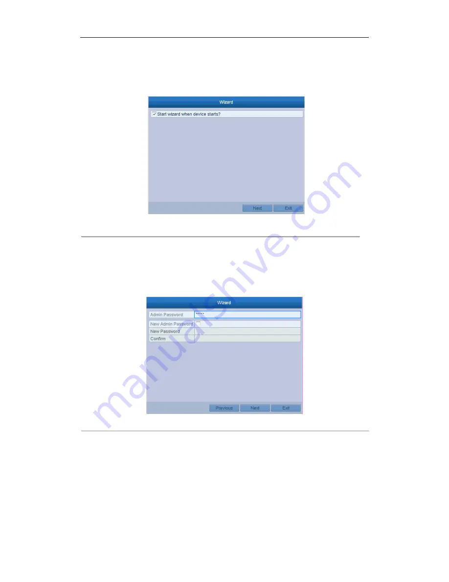
By default, the Setup Wizard starts once the NVR has loaded, as shown in Figure 2. 9. 

1


Figure 2. 9


Start Wizard Interface 


Operating the Setup Wizard: 

1.


The Setup Wizard can walk you through some important settings of the NVR. If you don’t want to use the 

Setup Wizard at that moment, click the Cancel button. You can also choose to use the Setup Wizard next 
time by leaving the “Start wizard when the device starts?” checkbox checked. 

2.


Click Next button to enter the date and time settings window, as shown in Figure 2. 10. 


Figure 2. 10


Date and Time Settings 


3.


After the time settings, click Next button which takes you back to the Network Setup Wizard window, as 

shown in the following figure. 

Summary of Contents for LV-N9600 Series

Page 1: ...Network Video Recorder User Manual ...

Page 2: ...NT WILL OUR COMPANY ITS DIRECTORS OFFICERS EMPLOYEES OR AGENTS BE LIABLE TO YOU FOR ANY SPECIAL CONSEQUENTIAL INCIDENTAL OR INDIRECT DAMAGES INCLUDING AMONG OTHERS DAMAGES FOR LOSS OF BUSINESS PROFITS BUSINESS INTERRUPTION OR LOSS OF DATA OR DOCUMENTATION IN CONNECTION WITH THE USE OF THIS PRODUCT EVEN IF OUR COMPANY HAS BEEN ADVISED OF THE POSSIBILITY OF SUCH DAMAGES REGARDING TO THE PRODUCT WITH...

Page 3: ...rference that may cause undesired operation EU Conformity Statement This product and if applicable the supplied accessories too are marked with CE and comply therefore with the applicable harmonized European standards listed under the EMC Directive 2004 108 EC the RoHS Directive 2011 65 EU 2012 19 EU WEEE directive Products marked with this symbol cannot be disposed of as unsorted municipal waste ...

Page 4: ...safety regulations of the nation and region Please refer to technical specifications for detailed information Input voltage should meet both the SELV Safety Extra Low Voltage and the Limited Power Source with 100 240 VAC or 12 VDC according to the IEC60950 1 standard Please refer to technical specifications for detailed information Do not connect several devices to one power adapter as adapter ove...

Page 5: ... properly secured to a rack or shelf Major shocks or jolts to the unit as a result of dropping it may cause damage to the sensitive electronics within the unit Use the device in conjunction with an UPS if possible Power down the unit before connecting and disconnecting accessories and peripherals A factory recommended HDD should be used for this device Improper use or replacement of the battery ma...

Page 6: ... 5 Thank you for purchasing our product If there is any question or request please do not hesitate to contact dealer The figures in the manual are for reference only This manual is applicable to the following models LV N9600 Series NVR ...

Page 7: ...uto switch are provided and the auto switch interval is configurable l Quick setting menu is provided for live view l Motion detection video tampering video exception alert and video loss alert functions l Privacy mask l Multiple PTZ protocols supported PTZ preset patrol and pattern l Zooming in by clicking the mouse and PTZ tracing by dragging mouse HDD Management l 2 SATA hard disks for LV N9600...

Page 8: ...e supported l TCP UDP and RTP for unicast l Auto Manual port mapping by UPnP TM l Extranet access by HiDDNS l Support access by Cloud P2P l Remote web browser access by HTTPS ensures high security l The ANR Automatic Network Replenishment function is supported it enables the IP camera save the recording files in the local storage when the network is disconnected and synchronizes the files to the N...

Page 9: ...User Manual of LV N9600 Series NVR 8 Development Scalability l SDK for Windows system l Source code of application software for demo l Development support and training for application system ...

Page 10: ... Online IP Cameras 35 2 6 3 Editing the Connected IP Cameras and Configuring Customized Protocols 38 2 6 4 Editing IP Cameras Connected to the PoE Interfaces 41 Chapter 3 Live View 44 3 1 Introduction of Live View 45 3 2 Operations in Live View Mode 46 3 2 1 Front Panel Operation on Live View 46 3 2 2 Using the Mouse in Live View 46 3 2 3 Using an Auxiliary Monitor 47 3 2 4 Quick Setting Toolbar i...

Page 11: ...Tag 95 6 1 6 Playing Back by Sub periods 98 6 1 7 Playing Back by System Logs 98 6 1 8 Playing Back External File 100 6 2 Auxiliary Functions of Playback 101 6 2 1 Playing Back Frame by Frame 101 6 2 2 Thumbnails View 101 6 2 3 Fast View 102 6 2 4 Digital Zoom 102 6 2 5 File Management 103 Chapter 7 Backup 105 7 1 Backing up Record Files 106 7 1 1 Quick Export 106 7 1 2 Backing up by Normal Video ...

Page 12: ...43 10 2 Behavior Search 144 10 3 Plate Search 145 10 4 People Counting 145 10 5 Heat Map 146 Chapter 11 Network Settings 148 11 1 Configuring General Settings 149 11 2 Configuring Advanced Settings 150 11 2 1 Configuring Cloud P2P 150 11 2 2 Configuring DDNS 150 11 2 3 Configuring NTP Server 152 11 2 4 Configuring SNMP 152 11 2 5 Configuring More Settings 153 11 2 6 Configuring Email 154 11 2 7 Co...

Page 13: ...arching Exporting Log Files 184 14 3 Importing Exporting IP Camera Info 186 14 4 Importing Exporting Configuration Files 187 14 5 Upgrading System 188 14 5 1 Upgrading by Local Backup Device 188 14 5 2 Upgrading by FTP 188 14 6 Restoring Default Settings 190 Chapter 15 Others 191 15 1 Configuring General Settings 192 15 2 Configuring DST Settings 193 15 3 Configuring More Settings 194 15 4 Managin...

Page 14: ...User Manual of LV N9600 Series NVR 13 Chapter 1 Introduction ...

Page 15: ...er input and functions of the composite keys Input letter or numbers when the light is out Realize functions when the light is red 5 Composite Keys 1 MENU Enter numeral 1 Access the main menu interface 2 ABC F1 Enter numeral 2 Enter letters ABC The F1 button when used in a list field will select all items in the list In PTZ Control mode it will turn on off PTZ light and when the image is zoomed in...

Page 16: ...Down buttons are used to speed up and slow down record playing and the Left and Right buttons are used to move the recording 30s forwards or backwards In the image setting interface the up and down button can adjust the level bar of the image parameters In live view mode these buttons can be used to switch channels ENTER The Enter button is used to confirm selection in menu mode or used to check c...

Page 17: ...R Remotes and DVRs On the DVR 1 Go to General More Settings 2 Type a number 255 digits maximum into the Device No field 3 On the IR Remote 4 Press the DEV button 5 Use the Number buttons to enter the Device ID that was entered into the DVR 6 Press Enter button to accept the new Device ID Figure 1 2 Remote Control Unpairing Disabling an IR Remote from a DVR To unpair an IR Remote from a DVR so that...

Page 18: ...iss the on screen keyboard 8 Press the OK button on the screen to accept input and display the Yes No verification prompt use Up Down Arrow buttons 12 to move between fields 9 Press Enter button 12 to accept selection User name password prompt depends on DVR is configuration See System Configuration section 2 DEV Enable IR Remote Press DEV button enter DVR Device ID with number keys press Enter to...

Page 19: ...front panel If there is no response after you press any button on the remote follow the procedure below to troubleshoot Steps 1 Go to Menu Settings General More Settings by operating the front control panel or the mouse 2 Check and remember NVR ID The default ID is 255 This ID is valid for all the IR remote controls 3 Press the DEV button on the remote control 4 Enter the NVR ID you set in step 2 ...

Page 20: ...ider The operation of the mouse Table 1 3 Description of the Mouse Control Name Action Description Left Click Single Click Live view Select channel and show the quick set menu Menu Select and enter Double Click Live view Switch between single screen and multi screen Click and Drag PTZ control pan tilt and zoom Video tampering privacy mask and motion detection Select target area Digital zoom in Dra...

Page 21: ...Description Figure 1 3 Soft Keyboard Description of the buttons on the soft keyboard Table 1 4 Description of the Soft Keyboard Icons Icons Description Icons Description English Capital English Numbers Symbols Lowercase Uppercase Backspace Space Enter Exit ...

Page 22: ...RM OUT Connector for alarm output 5 HDMIInterface HDMI video output connector 6 LAN Network Interface 1 10 100 1000 Mbps self adaptive Ethernet interface 7 USB Interface Universal Serial Bus USB 3 0 ports for additional devices such as USB mouse and USB Hard Disk Drive HDD 8 Ground Ground needs to be connected when NVR starts up 9 Power Supply 100 to 240 VAC power supply 10 Power Switch Switch for...

Page 23: ...User Manual of LV N9600 Series NVR 22 Chapter 2 Getting Started ...

Page 24: ...ng that the unit begins to start up 3 After startup the Power indicator LED remains blue A splash screen with the status of the HDD appears on the monitor The row of icons at the bottom of the screen shows the HDD status X means that the HDD is not installed or cannot be detected Shutting down the NVR Steps There are two proper ways to shut down the NVR Ÿ OPTION 1 Standard shutdown 1 Enter the Shu...

Page 25: ...TRONG PASSWORD RECOMMENDED We highly recommend you create a strong password of your own choosing Using a minimum of 8 characters including at least three of the following categories upper case letters lower case letters numbers and special characters in order to increase the security of your product And we recommend you reset your password regularly especially in the high security system resetting...

Page 26: ... for device login 2 3 1 Configuring the Unlock Pattern After the device is activated you can enter the following interface to configure the device unlock pattern Figure 2 3 Set Unlock Pattern Steps 1 Use the mouse to draw a pattern among the 9 dots on the screen Release the mouse when the pattern is done Figure 2 4 Draw the Pattern ...

Page 27: ... be connected for once only 2 Draw the same pattern again to confirm it When the two patterns match the pattern is configured successfully Figure 2 5 Confirm the Pattern If the two patterns are different you must set the pattern again Figure 2 6 Re set the Pattern 2 3 2 Logging in via Unlock Pattern ...

Page 28: ...igure 2 8 Figure 2 7 Draw the Unlock Pattern 2 Draw the pre defined pattern to unlock to enter the menu operation l If you have forgotten your pattern you can select the Forget My Pattern or Switch User option to enter the normal login dialog box l When the pattern you draw is different from the pattern you have configured you should try again l If you have drawn the wrong pattern for more than 5 ...

Page 29: ...t settings of the NVR If you don t want to use the Setup Wizard at that moment click the Cancel button You can also choose to use the Setup Wizard next time by leaving the Start wizard when the device starts checkbox checked 2 Click Next button to enter the date and time settings window as shown in Figure 2 10 Figure 2 10 Date and Time Settings 3 After the time settings click Next button which tak...

Page 30: ... the basic network parameters Then you will enter the Cloud P2P interface Configure the Cloud P2P according to your need Figure 2 12 Advanced Network Parameters 5 Click Next button after you configured the basic network parameters Then you will enter the Advanced Network Parameter interface You can enable UPnP DDNS and set other ports according to your need ...

Page 31: ...n the HDD 8 Click Next button You enter the Adding IP Camera interface 9 Click Search to search the online IP Camera and the Security status shows whether it is active or inactive Before adding the camera make sure the IP camera to be added is in active status If the camera is in inactive status you can click the inactive icon of the camera to set the password to activate it You can also select mu...

Page 32: ...heckbox of Enable H 265 the NVR can automatically switch to the H 265 stream of IP camera which supports H 265 video format for the initial access 10 Click Next button Configure the recording for the added IP Cameras Figure 2 16 Record Settings 11 Click OK to complete the startup Setup Wizard ...

Page 33: ... dropdown list Figure 2 17 Login Interface 2 Input Password 3 Click OK to log in In the Login dialog box if you enter the wrong password 7 times the current user account will be locked for 60 seconds Figure 2 18 User Account Protection 2 5 4 User Logout Purpose After logging out the monitor turns to the live view mode and if you want to perform any operations you need to enter user name and passwo...

Page 34: ...NVR 33 Steps 1 Enter the Shutdown menu Menu Shutdown Figure 2 19 Logout 2 Click Logout After you have logged out the system menu operation on the screen is invalid It is required to input a user name and password to unlock the system ...

Page 35: ...One touch Activate to activate the cameras in batch 3 Set the password of the camera to activate it Use Admin Password when you check the checkbox the camera s will be configured with the same admin password of the operating NVR Create New Password If the admin password is not used you must create the new password for the camera and confirm it STRONG PASSWORD RECOMMENDED We highly recommend you cr...

Page 36: ...ng Network Detection Adding the IP Cameras Ÿ OPTION 1 Steps 1 Click to select an idle window in the live view mode 2 Click the icon in the center of the windw to pop up the adding IP camera interface 3 Select the detected IP camera and click the Add button to add it directly and you can click the Search button to refresh the online IP camera manually Figure 2 21 Quick Adding IP Camera Interface Or...

Page 37: ...can click the One touch Adding button to add all cameras with the same login password from the list Make sure the camera to add has already been activated 4 For the encoders with multiple channels only check the Channel Port checkbox in the pop up window as shown in the following figure and click OK to add multiple channels Ÿ OPTION 3 Steps 1 On the IP Camera Management interface click the Custom ...

Page 38: ...ce Refer to the following table for the description of the icons Table 2 1 Description of Icons Icon Explanation Icon Explanation Edit basic parameters of the camera Add the detected IP camera The camera is disconnected you can click the icon to get the exception information of camera Delete the IP camera Play the live video of the connected camera Advanced settings of the camera Upgrade the conne...

Page 39: ...IP Cameras Enabling the H 265 Stream Access You can check the checkbox of Enable H 265 the NVR can automatically switch to the H 265 stream of IP camera which supports H 265 video format for the initial access 2 6 3 Editing the Connected IP Cameras and Configuring Customized Protocols After the adding of the IP cameras the basic information of the camera lists in the page you can configure the bas...

Page 40: ...t advanced parameters 1 Drag the horizontal scroll bar to the right side and click the icon 2 You can edit the network information and the password of the camera 3 Click OK to save the settings and exit the interface Configuring the customized protocols Purpose To connect the network cameras which are not configured with the standard protocols you can configure the customized protocols for them St...

Page 41: ... Path Example rtsp 192 168 1 55 554 ch1 main av_stream Ÿ Protocol Name Edit the name for the custom protocol Ÿ Enable Sub stream If the network camera does not support sub stream or the sub stream is not needed leave the checkbox empty Ÿ Type The network camera adopting custom protocol must support getting stream through standard RTSP Ÿ Transfer Protocol Select the transfer protocol for the custom...

Page 42: ...eras can be connected to 4P models 8 network cameras to 8P models and 16 network cameras to 16P models If you disable the PoE interface you can also connect to the online network cameras And the PoE interface supports the Plug and Play function Example If you want to connect 6 network cameras via PoE interfaces and 2 online cameras you must disable 2 PoE interfaces in the Edit IP Camera menu To ad...

Page 43: ...the Adding Method in the drop down list Plug and Play It means that the camera is connected to the PoE interface so in this case the parameters of the camera can t be edited The IP address of the camera can only be edited in the Network Configuration interface see Chapter 11 1 Configuring General Settings for detailed information Figure 2 30 Edit IP Camera Interface Plug and Play ...

Page 44: ...face by selecting the manual while the current channel can be used as a normal channel and the parameters can also be edited Input the IP address the user name and password of administrator manually and click OK to add the IP camera Figure 2 31 Edit IP Camera Interface Manual ...

Page 45: ...User Manual of LV N9600 Series NVR 44 Chapter 3 Live View ...

Page 46: ...ht of the screen for each channel showing the status of the record and alarm in the channel so that you can know whether the channel is recorded or whether there are alarms occur as soon as possible Table 3 1 Description of Live View Icons Icons Description Alarm video loss video tampering motion detection VCA and sensor alarm Record manual record schedule record motion detection VCA and alarm tri...

Page 47: ...aces The priority level for the main and aux output is HDMI1 VGA1 VGA for LV N9600 When both the HDMI and VGA are connected the HDMI is used as main output and the VGA is used as the aux output When the aux output is enabled the main output cannot perform any operation and you can do some basic operation on the live view mode for the Aux output 3 2 1 Front Panel Operation on Live View Table 3 2 Fr...

Page 48: ...or Switch to the auxiliary output mode and the operation for the main output is disabled Ÿ The dwell time of the live view configuration must be set before using Start Auto switch Ÿ If you enter Aux monitor mode and the Aux monitor is not connected the mouse operation is disabled you need to switch back to the Main output with the MAIN AUX button on the front panel or remote Ÿ If the corresponding...

Page 49: ...4 Description of Quick Setting Toolbar Icons Icons Description Icons Description Icons Description Enable Disable Manual Record Instant Playback Mute Audio on PTZ Control Digital Zoom Image Settings Close Live View Instant Playback only shows the record in last five minutes If no record is found it means there is no record during the last five minutes Digital Zoom is for zooming in the live image ...

Page 50: ...ategy can be selected to set strategy including Real time Balanced Fluency Face detection function can be used to detect the human faces in live view mode and save in HDD When there are human faces with the specified size detected in the front of the camera the device will capture the human face and save in HDD Move the mouse onto the icon to show the real time stream information including the fra...

Page 51: ...vailable in this menu include Video Output Interface Provide the HDMI and VGA video outputs Live View Mode Designates the display mode to be used for Live View Dwell Time The time in seconds to dwell between switching of channels when enabling auto switch in Live View Enable Audio Output Enables disables audio output for the selected video output Volume Adjust the volume of live view playback and ...

Page 52: ... on different models 2 Select the small window and double click on the channel number to display the channel on the window You can click button to start live view for all the channels and click to stop all the live view 3 Click the Apply button to save the setting You can also click and drag the camera to the desired window on the live view interface to set the camera order ...

Page 53: ...e image quality channel zero encoding is supported as an option for you Steps 1 Enter the Live View Settings interface Menu Configuration Live View 2 Select the Channel Zero Encoding tab Figure 3 8 Live View Channel Zero Encoding 3 Check the checkbox after Enable Channel Zero Encoding 4 Configure the Frame Rate Max Bitrate Mode and Max Bitrate After you set the Channel Zero encoding you can get a ...

Page 54: ...User Manual of LV N9600 Series NVR 53 Chapter 4 PTZ Controls ...

Page 55: ...ollow the procedure to set the parameters for PTZ The configuring of the PTZ parameters should be done before you control the PTZ camera Steps 1 Enter the PTZ Settings interface Menu Camera PTZ Figure 4 1 PTZ Settings 2 Click the PTZ Parameters button to set the PTZ parameters ...

Page 56: ...gure 4 2 PTZ General 3 Choose the camera for PTZ setting in the Camera dropdown list 4 Enter the parameters of the PTZ camera All the parameters should be exactly the same as the PTZ camera parameters 5 Click Apply button to save the settings ...

Page 57: ... the PTZ Control interface Menu Camera PTZ Figure 4 3 PTZ Settings 2 Use the directional button to wheel the camera to the location where you want to set preset and the zoom and focus operations can be recorded in the preset as well 3 Enter the preset No 1 255 in the preset text field and click the Set button to link the location to the preset Repeat the steps2 3 to save more presets You can click...

Page 58: ...how the PTZ control panel 2 Choose Camera in the dropdown list 3 Click the button to show the general settings of the PTZ control Figure 4 4 PTZ Panel General 4 Click to enter the preset No in the corresponding text field 5 Click the Call Preset button to call it 4 2 3 Customizing Patrols Purpose Patrols can be set to move the PTZ to different key points and have it stay there for a set duration b...

Page 59: ...preset The Key Point No determines the order at which the PTZ will follow while cycling through the patrol The Duration refers to the time span to stay at the corresponding key point The Speed defines the speed at which the PTZ will move from one key point to the next 5 Click the Add button to add the next key point to the patrol or you can click the OK button to save the key point to the patrol Y...

Page 60: ... the PTZ option in the right click menu to show the PTZ control panel 2 Click the button to show the general settings of the PTZ control Figure 4 7 PTZ Panel General 3 Select a patrol in the dropdown list and click the Call Patrol button to call it 4 You can click the Stop Patrol button to stop calling it 4 2 5 Customizing Patterns Purpose Patterns can be set by recording the movement of the PTZ Y...

Page 61: ...as the pattern 4 2 6 Calling Patterns Purpose Follow the procedure to move the PTZ camera according to the predefined patterns Steps 1 Click the button PTZ in the lower right corner of the PTZ setting interface Or press the PTZ button on the front panel or click the PTZ Control icon in the quick setting bar or select the PTZ option in the right click menu to show the PTZ control panel 2 Click the ...

Page 62: ... certain models Steps 1 Enter the PTZ Control interface Menu Camera PTZ Figure 4 10 PTZ Settings 2 Use the directional button to wheel the camera to the location where you want to set the limit and click the Left Limit or Right Limit button to link the location to the corresponding limit The speed dome starts linear scan from the left limit to the right limit and you must set the left limit on the...

Page 63: ... the linear scan and click the Linear Scan button again to stop it You can click the Restore button to clear the defined left limit and right limit data and the dome needs to reboot to make settings take effect 4 2 9 One touch Park Before operating this function make sure the connected camera supports the linear scan and is in protocol Purpose For some certain model of the speed dome it can be con...

Page 64: ...predefined preset 1 to preset 32 in order after the park time The undefined preset will be skipped Park Patrol 1 The dome starts move according to the predefined patrol 1 path after the park time Park Preset 1 The dome moves to the predefined preset 1 location after the park time The park time can only be set through the speed dome configuration interface by default the value is 5s 4 Click the but...

Page 65: ...option in the right click menu Click the Configuration button on the control panel and you can enter the PTZ Settings interface In PTZ control mode the PTZ panel will be displayed when a mouse is connected with the device If no mouse is connected the icon appears in the lower left corner of the window indicating that this camera is in PTZ control mode Figure 4 13 PTZ Panel Table 4 1 Description of...

Page 66: ...n Icon Description 3D Zoom Image Centralization Menu Switch to the PTZ control interface Switch to the one touch control interface Switch to the general settings interface Previous item Next item Start pattern patrol Stop the patrol pattern movement Exit Minimize windows ...

Page 67: ...User Manual of LV N9600 Series NVR 66 Chapter 5 Recording Settings ...

Page 68: ...Menu HDD General Figure 5 1 HDD General 2 Check the storage mode of the HDD 1 Click Advanced to check the storage mode of the HDD 2 If the HDD mode is Quota please set the maximum record capacity and maximum picture capacity For detailed information see Chapter Configuring Quota Mode 3 If the HDD mode is Group you should set the HDD group For detailed information see Chapter Configuring HDD Group ...

Page 69: ...the video encoding to H 265 or H 264 l Enable H 264 Mode check the checkbox to enable Once enabled the Max Bitrate Mode Max Bitrate Kbps and Max Bitrate Range Recommend are not configurable Enabling it helps to ensure the high video quality with a lowered bitrate The H 265 and H 264 should be supported by the connected IP camera 2 Click the More Settings button to set the advanced parameters for r...

Page 70: ...mined by the capacity of the HDD Redundant Record Capture By enabling redundant record or capture you save the record and captured picture in the redundant HDD See Chapter Configuring Redundant Recording Record Audio Check the checkbox to enable or disable audio recording Video Stream Main stream and sub stream are selectable for recording When you select sub stream you can record for a longer tim...

Page 71: ...apter 错误 未找到引用源 Ÿ The parameters of Main Stream Event are read only 3 Parameters Settings for Sub stream 1 Enter the Sub stream tab page Figure 5 5 Sub stream Parameters 2 Configure the parameters of the camera 3 Click Apply to save the settings ...

Page 72: ...le 1 Select Record Capture Schedule Figure 5 6 Record Schedule Different recording types are marked in different color icons Continuous scheduled recording Event recording triggered by all event triggered alarm Motion recording triggered by motion detection Alarm recording triggered by alarm M A recording triggered by either motion detection or alarm M A recording triggered by motion detection and...

Page 73: ... the schedule II To schedule an all day recording check the checkbox after the All Day item Figure 5 8 Edit Schedule III To arrange other schedule set the Start End time for each period Up to 8 periods can be configured for each day And the time periods can t be overlapped each other IV Select the record type in the dropdown list ...

Page 74: ...r 9 l The VCA settings are only available to the smart IP cameras Repeat the above edit schedule steps to schedule recording or capture for other days in the week If the schedule can also be applied to other days click Copy Figure 5 9 Copy Schedule to Other Days V Click OK to save setting and back to upper level menu VI Click Apply in the Record Schedule interface to save the settings Draw the sch...

Page 75: ... the Apply button to validate the settings 3 Optional If the settings can also be used to other channels click Copy and then choose the channel to which you want to copy 4 Click Apply to save the settings Figure 5 11 Copy Schedule to Other Channels ...

Page 76: ... surveillance center and so on In this chapter you can follow the steps to schedule a record which triggered by the detected motion Steps 1 Enter the Motion Detection interface Menu Camera Motion Figure 5 12 Motion Detection 2 Configure Motion Detection 1 Choose camera you want to configure 2 Check the checkbox after Enable Motion Detection 3 Drag and draw the area for motion detection by mouse If...

Page 77: ...ch you want the motion detection event to trigger recording 6 Click Apply to save the settings 7 Click OK to back to the upper level menu 8 Exit the Motion Detection menu 3 Edit the Motion Detection Record Schedule For the detailed information of schedule configuration see Chapter Configuring Recording ...

Page 78: ...7 5 4 Configuring Alarm Triggered Recording Purpose Follow the procedure to configure alarm triggered recording or capture Steps 1 Enter the Alarm settings interface Menu Configuration Alarm Figure 5 14 Alarm Settings 2 Click Alarm Input ...

Page 79: ...r alarm type 3 Check the checkbox for Setting 4 Click Settings 5 Choose the alarm triggered recording channel 6 Check the checkbox to select channel 7 Click Apply to save settings 8 Click OK to back to the upper level menu Repeat the above steps to configure other alarm input parameters If the settings can also be applied to other alarm inputs click Copy and choose the alarm input number ...

Page 80: ... LV N9600 Series NVR 79 Figure 5 16 Copy Alarm Input 3 Edit the Alarm triggered record in the Record Schedule setting interface For the detailed information of schedule configuration see Chapter Configuring Recording ...

Page 81: ...e is prior to the scheduled recording and capture Steps 1 Enter the Manual settings interface Menu Manual Or press the REC SHOT button on the front panel Figure 5 17 Manual Record 2 Enable the Manual Recording 1 Select Record on the left bar 2 Click the status button before camera number to change to 3 Disable manual record Click the status button to change to Green icon means that the channel is ...

Page 82: ...o configure the record or capture schedule on holiday for that year You may want to have different plan for recording and capture on holiday Steps 1 Enter the Record setting interface Menu Record Holiday Figure 5 18 Holiday Settings 2 Enable Edit Holiday schedule 1 Click to enter the Edit interface ...

Page 83: ... Holiday 3 Select Mode from the dropdown list There are three different modes for the date format to configure holiday schedule 4 Set the start and end date 5 Click Apply to save settings 6 Click OK to exit the Edit interface 3 Enter Record Schedule settings interface to edit the holiday recording schedule ...

Page 84: ...fety and reliability Steps 1 Enter HDD Information interface Menu HDD Figure 5 20 HDD General 2 Enter the Record setting interface Menu Record Parameters 1 Select Record tab Figure 5 21 Encoding Record 2 Click More Settings to enter the following interface 3 Select Camera you want to configure in the drop down list 4 Check the checkbox of Redundant Record 5 Click OK to save settings and back to th...

Page 85: ...left side menu 4 Click to enter editing interface 5 Configuring HDD group 1 Choose a group number for the HDD group 2 Click Apply and then in the pop up message box click Yes to save your settings 3 Click OK to back to the upper level menu Repeat the above steps to configure more HDD groups 6 Choose the Channels which you want to save the record files and captured pictures in the HDD group 1 Selec...

Page 86: ...rface Menu Playback 2 Check the checkbox of channel s in the channel list and then double click to select a date on the calendar Figure 5 24 Normal Playback 3 During playback click the button to lock the current recording file In the multi channel playback mde clicking the button will lock all the record files related to the playback channels 4 You can click the button to pop up the file managemen...

Page 87: ...click to change it to to unlock the file and the file is not protected l Lock File when Export Steps 1 Enter Export setting interface Menu Export Figure 5 26 Export 2 Select the channels you want to search by checking the checkbox to 3 Configure the record type file type start end time 4 Click Search to show the results ...

Page 88: ...ind the record files you want to protect and then click the icon which will turn to indicating that the file is locked The record files of which the recording is still not completed cannot be locked 2 Click to change it to to unlock the file and the file is not protected Figure 5 28 Unlocking Attention ...

Page 89: ...User Manual of LV N9600 Series NVR 88 Chapter 6 Playback ...

Page 90: ...el in live view mode and click the button in the quick setting toolbar In the instant playback mode only record files recorded during the last five minutes on this channel will be played back Figure 6 1 Instant Playback Interface 6 1 2 Playing Back by Normal Search Playback by Channel Enter the Playback interface right click a channel in live view mode and select Playback from the menu as shown in...

Page 91: ...itch are supported Steps 1 Enter playback interface Menu Playback 2 Check the checkbox of channel s in the channel list and then double click to select a date on the calendar Figure 6 3 Playback Calendar If there are record files for that camera in that day in the calendar the icon for that day is displayed as Otherwise it is displayed as Playback Interface You can use the toolbar in the bottom pa...

Page 92: ...ouse to click any point of the progress bar or drag the progress bar to locate specific frames Table 6 1 Detailed Explanation of Playback Toolbar Item Button Operation Button Operation Smart Search Set full screen for motion detection Draw line for the line crossing detection Draw quadrilateral for the intrusion detection Filter video files by setting the target characters Operations Audio on Mute...

Page 93: ... it with green color and play it in the normal speed while the video without motion will be played in the 16 time speed The smart playback rules and areas are configurable Before you start To get the smart search result the corresponding event type must be enabled and configured on the IP camera Here we take the intrusion detection as an example 1 Log in the IP camera by the web browser and enable...

Page 94: ...ick the to set the full screen full screen as the detection area l Line Crossing Detection Select the button and click on the image to specify the start point and end point of the line l Intrusion Detection Click the button and specify 4 points to set a quadrilateral region for intrusion detection Only one region can be set l Motion Detection Click the button and then click and draw the mouse to s...

Page 95: ...ase refer to Chapter 9 VCA Alarm for the details of VCA detection types For configuring the VCA recording please refer to Chapter 5 4 Configuring VCA Event Recording and Capture and for details of VCA detection types please refer to Chapter 9 VCA Alarm 5 Select the camera s for searching and set the Start time and End time 6 Click Search button to get the search result information You may refer to...

Page 96: ...ing Back by Tag Purpose Video tag allows you to record related information like people and location of a certain time point during playback You can use video tag s to search for record files and position time point Before playing back by tag 1 Enter Playback interface Menu Playback 2 Search and play back the record file s Refer to Chapter 6 1 1 for the detailed information about searching and play...

Page 97: ...to a single video file 3 Tag management Click button to enter the File Management interface and click Tag to manage the tags You can check edit and delete tag s Figure 6 11 Tag Management Interface Playing back by Tag Steps 1 Select the Tag from the drop down list in the Playback interface 2 Choose channels edit start time and end time and then click Search to enter Search Result interface ...

Page 98: ... command 3 Click button to play back the selected tag file You can click the Back button to back to the search interface Figure 6 13 Interface of Playback by Tag Pre play and post play can be configured You can click or button to select the previous or next tag Please refer to Table 6 1 for the description of buttons on the toolbar ...

Page 99: ... Up to 16 screens are configurable Figure 6 14 Interface of Sub periods Playback According to the defined number of split screens the video files on the selected date can be divided into average segments for playback E g if there are video files existing between 16 00 and 22 00 and the 6 screen display mode is selected then it can play the video files for 1 hour on each screen simultaneously 6 1 7...

Page 100: ...3 Choose a log with record file and click button to enter Playback interface If there is no record file at the time point of the log the message box No result found will pop up Figure 6 16 Result of System Log Search 4 Playback interface The toolbar in the bottom part of Playback interface can be used to control playing process ...

Page 101: ...n the external devices Steps 1 Enter Tag Search interface Menu Playback 2 Select the External File in the drop down list on the top left side The files are listed in the right side list You can click the button to refresh the file list 3 Select and click the button to play back it And you can adjust the playback speed by clicking and Figure 6 18 Interface of External File Playback ...

Page 102: ...playback of the record file click button until the speed changes to Single frame and one click on the playback screen represents reverse playback of one frame It is also feasible to use button in toolbar Using the Front Panel Click the button to set the speed to Single frame One click on button one click on the playback screen or Enter button on the front panel represents playback or reverse playb...

Page 103: ...er the playback interface and start to play the video files Figure 6 20 Playback Interface 2 Use the mouse to hold and drag through the playing time bar to fast view the video files 3 Release the mouse to the required time point to enter the full screen playback The fast view is supported only in the 1X single camera playback mode 6 2 4 Digital Zoom Steps 1 Click the button on the playback control...

Page 104: ...e the video clips captured pictures in playback locked files and tags you have added in the playback mode Steps 1 Enter the playback interface 2 Click on the toolbar to enter the file management interface Figure 6 22 File Management 3 You can view the saved video clips captured playback pictures lock unlock the files and edit the tags which you added in the playback mode ...

Page 105: ...User Manual of LV N9600 Series NVR 104 4 If required select the items and click Export All or Export to export the clips pictures files tags to local storage device ...

Page 106: ...User Manual of LV N9600 Series NVR 105 Chapter 7 Backup ...

Page 107: ...k Export button The time duration of record files on a specified channel cannot exceed one day Otherwise the message box Max 24 hours are allowed for quick export will pop up Figure 7 1 Quick Export Interface 2 Select the format of the log files to be exported Up to 9 formats are selectable 3 Click the Export to start exporting Here we use USB Flash Drive and please refer to the next section Norma...

Page 108: ...NVR 107 Figure 7 2 Quick Export using USB1 1 Stay in the Exporting interface until all record files are exported Figure 7 3 Export Finished 4 Check backup result Choose the record file in Export interface and click button to check it ...

Page 109: ... flash drives USB HDDs USB writer SATA writer Backup using USB flash drives and USB HDDs Steps 1 Enter Export interface Menu Export Normal 2 Select the cameras to search 3 Set search condition and click Search button to enter the search result interface The matched video files or pictures are displayed in Chart or List display mode Figure 7 5 Normal Video Search for Backup 4 Select video files or ...

Page 110: ...of Normal Video Search for Backup 5 Export the video files or picture files Click Export All button to export all the files Or you can select recording files you want to back up and click Export button to enter Export interface If the inserted USB device is not recognized Click the Refresh button Reconnect device Check for compatibility from vendor You can also format USB flash drives or USB HDDs ...

Page 111: ...7 8 Export Finished The backup of video files using USB writer or SATA writer has the same operating instructions Please refer to steps described above 7 1 3 Backing up by Event Search Purpose Back up event related record files using USB devices USB flash drives USB HDDs USB writer SATA writer Quick Backup and Normal Backup are supported Steps 1 Enter Export interface Menu Export Event 2 Select th...

Page 112: ...rt the video files Please refer to step5 of Chapter 7 1 2 Backing up by Normal Video Search for details 7 1 4 Backing up Video Clips Purpose You may also select video clips or captured pictures in playback mode to export directly during Playback using USB devices USB flash drives USB HDDs USB writer SATA writer Steps 1 Enter Playback interface Please refer to Chapter 6 1 Playing Back Record Files ...

Page 113: ...se refer to step5 of Chapter Backing up by Normal Video Search for details 7 2 Managing Backup Devices Management of USB flash drives USB HDDs Steps 1 Enter the Export interface Figure 7 12 Storage Device Management 2 Backup device management Click New Folder button if you want to create a new folder in the backup device ...

Page 114: ...and click button if you want to delete it Click Erase button if you want to erase the files from a re writable CD DVD Click Format button to format the backup device If the inserted storage device is not recognized Click the Refresh button Reconnect device Check for compatibility from vendor ...

Page 115: ...ing device fails the hot spare device switches into operation thus increasing the reliability of the system Please contact dealer for details of models which support the hot spare function Before you start At least 2 devices are online A bidirectional connection shown in the figure below is required to be built between the hot spare device and each working device Figure 7 13 Building Hot Spare Sys...

Page 116: ...User Manual of LV N9600 Series NVR 115 Chapter 8 Alarm Settings ...

Page 117: ...y Click button and set alarm response actions 3 Click Trigger Channel tab and select one or more channels which will start to record capture or become full screen monitoring when motion alarm is triggered and click Apply to save the settings Figure 8 1 Set Trigger Camera of Motion Detection 4 Set up arming schedule of the channel 1 Select Arming Schedule tab to set the arming schedule of handling ...

Page 118: ...5 Click Handling tab to set up alarm response actions of motion alarm please refer to Chapter Setting Alarm Response Actions 6 If you want to set motion detection for another channel repeat the above steps or just click Copy in the Motion Detection interface to copy the above settings to it ...

Page 119: ...Alarm Status Interface of System Configuration 2 Set up the handling action of the selected alarm input Check the Enable checkbox and click Settings button to set up its alarm response actions Figure 8 4 Alarm Input Setup Interface 3 Select Trigger Channel tab and select one or more channels which will start to record capture or become full screen monitoring when an external alarm is input and cli...

Page 120: ...e Copy button to copy an arming schedule to other days 5 Select Linkage Action tab to set up alarm response actions of the alarm input please refer to Chapter Setting Alarm Response Actions 6 If necessary select PTZ Linking tab and set PTZ linkage of the alarm input Set PTZ linking parameters and click OK to complete the settings of the alarm input Please check whether the PTZ or speed dome suppor...

Page 121: ...Alarm Input 7 If you want to set handling action of another alarm input repeat the above steps Or you can click the Copy button on the Alarm Input Setup interface and check the checkbox of alarm inputs to copy the settings to them Figure 8 7 Copy Settings of Alarm Input ...

Page 122: ...ure 8 8 Video Loss Setup Interface 2 Set up handling action of video loss Check the checkbox of Enable Video Loss Alarm and click button to set up handling action of video loss 3 Set up arming schedule of the handling actions 1 Select Arming Schedule tab to set the channel s arming schedule 2 Choose one day of a week and up to eight time periods can be set within each day 3 Click Apply button to s...

Page 123: ...ure 8 9 Set Arming Schedule of Video Loss 4 Select Linkage Action tab to set up alarm response action of video loss please refer to Chapter Setting Alarm Response Actions 5 Click the OK button to complete the video loss settings of the channel ...

Page 124: ...ndling action of the channel Check the checkbox of Enable Video Tampering Detection Drag the sensitivity bar to set a proper sensitivity level Use the mouse to draw an area you want to detect video tampering Click button to set up handling action of video tampering 3 Set arming schedule and alarm response actions of the channel 1 Click Arming Schedule tab to set the arming schedule of handling act...

Page 125: ...t Arming Schedule of Video Tampering 4 Select Linkage Action tab to set up alarm response actions of video tampering alarm please refer to Chapter Setting Alarm Response Actions 5 Click the OK button to complete the video tampering settings of the channel ...

Page 126: ...cable IP Conflicted Duplicated IP address Illegal Login Incorrect user ID or password Record Capture Exception No space for saving recorded files or captured images Hot Spare Exception Disconnected with the working device Steps Enter Exception interface of System Configuration and handle various exceptions Menu Configuration Exceptions Please refer to Chapter Setting Alarm Response Actions for det...

Page 127: ...image And you can click the hint icon to check the details Besides the event to be displayed is configurable Steps 1 Enter the Exception settings interface Menu Configuration Exceptions 2 Check the checkbox of Enable Event Hint Figure 8 13 Event Hint Settings Interface 3 Click the to set the type of event to be displayed on the image Figure 8 14 Event Hint Settings Interface 4 Click the OK button ...

Page 128: ...t occurs The alarm host refers to the PC installed with Remote Client The alarm signal will be transmitted automatically at detection mode when remote alarm host is configured Email Linkage Send an email with alarm information to a user or users when an alarm is detected Trigger Alarm Output Trigger an alarm output when an alarm is triggered 1 Enter Alarm Output interface Menu Configuration Alarm ...

Page 129: ...teps to set up arming schedule of other days of a week You can also use Copy button to copy an arming schedule to other days Click the OK button to complete the video tampering settings of the alarm output No 4 You can also copy the above settings to another channel Figure 8 17 Copy Settings of Alarm Output ...

Page 130: ...alarm can be cleared only by clicking Clear button in the following interface Steps Select the alarm output you want to trigger or clear and make related operations Menu Manual Alarm Click Trigger Clear button if you want to trigger or clear an alarm output Click Trigger All button if you want to trigger all alarm outputs Click Clear All button if you want to clear all alarm output Figure 8 18 Cle...

Page 131: ...User Manual of LV N9600 Series NVR 130 Chapter 9 VCA Alarm ...

Page 132: ...f Enable Face Recognition 3 Click Save to save the settings Figure 9 1 Face Recognition 9 2 Face Detection Purpose Face detection function detects the face appears in the surveillance scene and some certain actions can be taken when the alarm is triggered Steps 1 Enter the VCA settings interface Menu Camera VCA 2 Select the camera to configure the VCA You can click the checkbox of Save VCA Picture...

Page 133: ... upload picture and overlay content settings Up to 4 lanes are selectable 7 Click Save to save the settings Please refer to the User Manual of Network Camera for the detailed instructions for the vehicle detection 9 4 Line Crossing Detection Purpose This function can be used for detecting people vehicles and objects cross a set virtual line The line crossing direction can be set as bidirectional f...

Page 134: ...ne from the B side to the A side can be detected 2 Click and drag the slider to set the detection sensitivity Sensitivity Range 1 100 The higher the value is the more easily the detection alarm can be triggered 3 Click OK to save the rule settings and back to the line crossing detection settings interface Figure 9 2 Set Line Crossing Detection Rules 7 Click and set two points in the preview window...

Page 135: ...User Manual of LV N9600 Series NVR 134 8 Click Apply to activate the settings ...

Page 136: ...the region When the duration of the object in the defined detection area is longer than the set time the alarm will be triggered 2 Click and drag the slider to set the detection sensitivity Sensitivity Range 1 100 The value of the sensitivity defines the size of the object which can trigger the alarm The higher the value is the more easily the detection alarm can be triggered 3 Percentage Range 1 ...

Page 137: ...User Manual of LV N9600 Series NVR 136 Figure 9 5 Draw Area for Intrusion Detection 8 Click Apply to save the settings ...

Page 138: ...nge 0 100 The higher the value is the more easily the detection alarm can be triggered 7 Click and draw a quadrilateral in the preview window by specifying four vertexes of the detection region and right click to complete drawing Only one region can be configured You can use the to clear the existing virtual line and re draw it Up to 4 rules can be configured 8 Click Apply to save the settings 9 7...

Page 139: ...percentage is small the alarm can be triggered when small number of people gathered in the defined detection region l Up to 4 rules can be configured 9 10 Fast Moving Detection Purpose Fast moving detection alarm is triggered when people vehicle or other objects move fast in a pre defined virtual region and a series of actions can be taken when the alarm is triggered l Please refer to the Chapter ...

Page 140: ...an be configured 9 13 Object Removal Detection Purpose Object removal detection function detects the objects removed from the pre defined region such as the exhibits on display and a series of actions can be taken when the alarm is triggered l Please refer to the Chapter 9 4 Intrusion Detection for operating steps to configure the object removal detection l The Threshold 5s 20s in the Rule Setting...

Page 141: ...he checkbox of Sudden Decrease of Sound Intensity Detection to detect the sound steep drop in the surveillance scene You can set the detection sensitivity 1 100 for sound steep drop 6 Click Apply to activate the settings 9 15 Sudden Scene Change Detection Purpose Scene change detection function detects the change of surveillance environment affected by the external factors such as the intentional ...

Page 142: ... the VCA settings interface Menu Camera VCA 2 Select the camera to configure the VCA You can click the checkbox of Save VCA Picture to save the captured pictures of VCA detection 3 Select the VCA detection type to PIR Alarm 4 Click to configure the trigger channel arming schedule and linkage action for the PIR alarm 5 Click the Rule Settings button to set the rules Please refer to the Chapter Face...

Page 143: ...User Manual of LV N9600 Series NVR 142 Chapter 10 VCA Search ...

Page 144: ... search Figure 10 1 Face Search 3 Specify the start time and end time for search the captured face pictures or video files 4 Click Search to start searching The search results of face detection pictures are displayed in list or in chart 5 Play the face picture related video file You can double click on a face picture to play its related video file in the view window on the top right or select a pi...

Page 145: ...etection unattended baggage detection object removal detection region entrance detection region exiting detection parking detection loitering detection people gathering detection and fast moving detection 5 Click Search to start searching The search results of pictures are displayed in list or in chart 6 Play the behavior analysis picture related video file You can double click on a picture from t...

Page 146: ...nu VCA Search Plate Search 2 Select the camera s for the plate search 3 Specify the start time and end time for searching the matched plate pictures Figure 10 3 Plate Search 4 Select the country from the drop down list for searching the location of the vehicle plate 5 Input the plate No in the field for search 7 Click Search to start searching The search results of detected vehicle plate pictures ...

Page 147: ...e 5 Click the Counting button to start people counting statistics Figure 10 4 People Counting Interface 6 You can click the Export button to export the statistics report in excel format 10 5 Heat Map Purpose Heat map is a graphical representation of data represented by colors The heat map function is usually used to analyze the visit times and dwell time of customers in a configured area The heat ...

Page 148: ...e 5 Click the Counting button to export the report data and start heat map statistics and the results are displayed in graphics marked in different colors As shown in the figure above red color block 255 0 0 indicates the most welcome area and blue color block 0 0 255 indicates the less popular area 6 You can click the Export button to export the statistics report in excel format ...

Page 149: ...User Manual of LV N9600 Series NVR 148 Chapter 11 Network Settings ...

Page 150: ...nfigure the internal NIC address so that IP addresses are assigned to the cameras connected to the PoE interfaces 4 After having configured the general settings click Apply button to save the settings Working Mode Two 10M 100M 1000M NIC cards are provided and it allows the device to work in the Multi address and Net fault Tolerance modes Multi address Mode The parameters of the two NIC cards can b...

Page 151: ...t server address is dev hicloudcam com 5 To turn the Enable Stream Encryption on you can select its checkbox 6 Enter the Verification Code of the device The verification code consists of 6 capital letters and is located at the bottom of the DVR You can also use the scanning tool of your phone to quickly get the code by scanning the QR code below Figure 11 2 Cloud P2P Settings Interface 7 Click the...

Page 152: ...he Device Domain Name text field enter the domain obtained from the DynDNS website 3 Enter the User Name and Password registered in the DynDNS website Figure 11 4 DynDNS Settings Interface PeanutHull Enter the User Name and Password obtained from the PeanutHull website Figure 11 5 PeanutHull Settings Interface NO IP Enter the account information in the corresponding fields Refer to the DynDNS sett...

Page 153: ... actions with NTP server The unit is minute NTP Server IP address of NTP server NTP Port Port of NTP server 5 Click the Apply button to save and exit the interface The time synchronization interval can be set from1 to 10080min and the default value is 60min If the NVR is connected to a public network you should use a NTP server that has a time synchronization function such as the server at the Nat...

Page 154: ...Select the More Settings tab to enter the More Settings interface Figure 11 9 More Settings Interface 3 Configure the remote alarm host server port HTTP port multicast RTSP port l Alarm Host IP Port With a remote alarm host configured the device will send the alarm event or exception message to the host when an alarm is triggered The remote alarm host must have the CMS Client Management System sof...

Page 155: ...mote IE access 4 Click the Apply button to save and exit the interface 11 2 6Configuring Email Purpose The system can be configured to send an Email notification to all designated users if an alarm event is detected etc an alarm or motion event is detected or the administrator password is changed Before configuring the Email settings the NVR must be connected to a local area network LAN that maint...

Page 156: ...ached alarm images The interval is the time of two adjacent alarm images You can also set SMTP port and enable SSL here Interval The interval refers to the time between two actions of sending attached pictures 6 Click Apply button to save the Email settings 7 You can click Test button to test whether your Email settings work 11 2 7Configuring NAT Purpose Two ways are provided for port mapping to r...

Page 157: ...ttings Finished Auto OPTION 2 Manual If you select Manual as the mapping type you can edit the external port on your demand by clicking to activate the External Port Settings dialog box Steps 1 Select Manual in the drop down list of Mapping Type 2 Click to activate the External Port Settings dialog box Configure the external port No for server port http port RTSP port and https port respectively l...

Page 158: ...rnal port and external port in the interface of Forwarding Steps 1 Enter the Network Settings interface Menu Configuration Network 2 Select the NAT tab to enter the port mapping interface 3 Leave the Enable UPnP checkbox unchecked 4 Click to activate the External Port Settings dialog box Configure the external port No for server port http port RTSP port and https port respectively The value of the...

Page 159: ...ed contents Each item should be corresponding with the device port including server port http port RTSP port and https port Figure 11 17 Setting Virtual Server Item The above virtual server setting interface is for reference only it may be different due to different router manufactures Please contact the manufacture of router if you have any problems with setting virtual server 11 3 Checking Netwo...

Page 160: ...User Manual of LV N9600 Series NVR 159 Figure 11 18 Network Traffic Interface 2 You can view the sending rate and receiving rate information on the interface The traffic data is refreshed every 1 second ...

Page 161: ...n the text field of Destination Address 4 Click Test button to start testing network delay and packet loss The testing result pops up on the window If the testing is failed the error message box will pop up as well Refer to the below Figure 11 20 Testing Result of Network Delay and Packet Loss 11 4 2Exporting Network Packet Purpose By connecting the NVR to network the captured network data packet ...

Page 162: ... is incorrect Figure 11 21 Export Network Packet 4 Click Export button to start exporting 5 After the exporting is complete click OK to finish the packet export as shown in below Figure 11 22 Packet Export Attention Up to 1M data can be exported each time 11 4 3Checking the Network Status Purpose You can also check the network status and quick set the network parameters in this interface Steps Cli...

Page 163: ...f the message box pops out with other information instead of this one you can click Network button to show the quick setting interface of the network parameters 11 4 4Checking Network Statistics Purpose You can check the network status to obtain the real time information of NVR Steps 1 Enter the Network Detection interface Menu Maintenance Net Detect 2 Choose the Network Stat tab ...

Page 164: ... Figure 11 25 Network Stat Interface 3 Check the bandwidth of IP Camera bandwidth of Remote Live View bandwidth of Remote Playback bandwidth of Net Receive Idle and bandwidth of Net Send Idle 4 You can click Refresh to get the newest status ...

Page 165: ...Yes button to initialize it immediately or you can perform the following steps to initialize the HDD Steps 1 Enter the HDD Information interface Menu HDD General Figure 12 1 HDD Information Interface 2 Select HDD to be initialized 3 Click the Init button Figure 12 2 Confirm Initialization 4 Select the OK button to start initialization Figure 12 3 Status changes to Initializing 5 After the HDD has ...

Page 166: ...User Manual of LV N9600 Series NVR 165 Figure 12 4 HDD Status Changes to Normal Initializing the HDD will erase all data on it ...

Page 167: ...e Add button to enter the Add NetHDD interface as shown Figure 12 6 HDD Information Interface 3 Add the allocated NetHDD 4 Select the type to NAS or IP SAN 5 Configure the NAS or IP SAN settings Add NAS disk 1 Enter the NetHDD IP address in the text field 2 Click the Search button to search the available NAS disks 3 Select the NAS disk from the list shown below Or you can just manually enter the d...

Page 168: ...tton to search the available IP SAN disks 3 Select the IP SAN disk from the list shown below 4 Click the OK button to add the selected IP SAN disk Up to 1 IP SAN disk can be added Figure 12 8 Add IP SAN Disk 6 After having successfully added the NAS or IP SAN disk return to the HDD Information menu The added NetHDD will be displayed in the list ...

Page 169: ...User Manual of LV N9600 Series NVR 168 If the added NetHDD is uninitialized please select it and click the Init button for initialization ...

Page 170: ...ough HDD settings Steps 1 Enter the Storage Mode interface Menu HDD Advanced Storage Mode 2 Set the Mode to Group as shown Figure 12 9 Storage Mode Interface 3 Click the Apply button and the following Attention box will pop up 4 Click the Yes button to reboot the device to activate the changes 5 Click the OK button to confirm the settings 6 In the pop up Attention box click the Yes button to finis...

Page 171: ...shown The NVR must be rebooted to enable the changes to take effect Figure 12 10 Storage Mode Settings Interface 3 Select a camera for which you want to configure quota 4 Enter the storage capacity in the text fields of Max Record Capacity GB and Max Picture Capacity GB as shown Figure 12 11 Configure Record Picture Quota 5 You can copy the quota settings of the current camera to other cameras if ...

Page 172: ...e quota settings You can also click the checkbox of IP Camera to select all cameras 7 Click the OK button to finish the Copy settings and back to the Storage Mode interface 8 Click the Apply button to apply the settings If the quota capacity is set to 0 then all cameras will use the total capacity of HDD for record and picture capture ...

Page 173: ...the status of each HDD which is displayed on the list as shown Figure 12 13 View HDD Status 1 If the status of HDD is Normal or Sleeping it works normally If the status is Uninitialized or Abnormal please initialize the HDD before use And if the HDD initialization is failed please replace it with a new one Checking HDD Status in HDD Information Interface Steps 1 Enter the System Information interf...

Page 174: ...User Manual of LV N9600 Series NVR 173 Figure 12 14 View HDD Status 2 ...

Page 175: ...gs Steps 1 Enter the S M A R T Settings interface Menu Maintenance HDD Detect 2 Select the HDD to view its S M A R T information list as shown in Figure 12 15 S M A R T Settings Interface The related information of the S M A R T is shown on the interface You can choose the self test types as Short Test Expanded Test or the Conveyance Test Click the start button to start the S M A R T HDD self eval...

Page 176: ... No in the dropdown list you want to configure and choose All Detection or Key Area Detection as the detection type 3 Click the Detect button to start the detection And you can click Error info button to see the detailed damage information And you can also pause resume or cancel the detection ...

Page 177: ...Error from the dropdown list 3 Click the checkbox s below to select the HDD error alarm type s as shown The alarm type can be selected to Audible Warning Notify Surveillance Center Send Email and Trigger Alarm Output Please refer to Chapter Setting Alarm Response Actions Figure 12 16 Configure HDD Error Alarm 4 When the Trigger Alarm Output is selected you can also select the alarm output to be tr...

Page 178: ...User Manual of LV N9600 Series NVR 177 Chapter 13 Camera Settings ...

Page 179: ...nu Camera OSD 2 Select the camera to configure OSD settings 3 Edit the Camera Name in the text field 4 Configure the Display Name Display Date and Display Week by clicking the checkbox 5 Select the Date Format Time Format and Display Mode Figure 13 1 OSD Configuration Interface 6 You can use the mouse to click and drag the text frame on the preview window to adjust the OSD position 7 Click the App...

Page 180: ...y Mask 2 Select the camera to set privacy mask 3 Click the checkbox of Enable Privacy Mask to enable this feature Figure 13 2 Privacy Mask Settings Interface 4 Use the mouse to draw a zone on the window The zones will be marked with different frame colors Up to 4 privacy masks zones can be configured and the size of each area can be adjusted 5 The configured privacy mask zones on the window can be...

Page 181: ...User Manual of LV N9600 Series NVR 180 Figure 13 3 Set Privacy Mask Area 6 Click the Apply button to save the settings ...

Page 182: ...ters 3 Adjust the slider or click on the up down arrow to set the value of the brightness contrast or saturation 4 Select the Enable Rotate function to Clockwise 270 degrees or OFF When OFF is selected the image is restored to original 5 Select the Mirror Mode to Left Right Up Down Center or OFF When OFF is selected the image is restored to original l The Rotate and Mirror functions must be suppor...

Page 183: ...User Manual of LV N9600 Series NVR 182 Chapter 14 NVR Management and Maintenance ...

Page 184: ...stem Information interface Menu Maintenance System Info 2 You can click the Device Info Camera Record Alarm Network and HDD tabs to view the system information of the device Figure 14 1 Device Information Interface You can add the device to your mobile client software via scanning the QR Code ...

Page 185: ...an be viewed and exported at any time Steps 1 Enter the Log Search interface Menu Maintenance Log Information Figure 14 2 Log Search Interface 2 Set the log search conditions to refine your search including the Start Time End Time Major Type and Minor Type 3 Click the Search button to start search log files 4 The matched log files will be displayed on the list shown below ...

Page 186: ... view its detailed information as shown And you can also click the button to view the related video files if available Figure 14 4 Log Details 6 If you want to export the log files click the Export button to enter the Export menu You can also click Export All on the Log Search interface to enter the Export interface and all the system logs will be exported to the backup device ...

Page 187: ...ormation of added IP camera can be generated into an excel file and exported to the local device for backup including the IP address manage port password of admin etc And the exported file can be edited on your PC like adding or deleting the content and copy the setting to other devices by importing the excel file to it Steps 1 Enter the camera management interface Menu Camera IP Camera Import Exp...

Page 188: ...arameters Steps 1 Enter the Import Export Configuration File interface Menu Maintenance Import Export Figure 14 6 Import Export Config File 2 Click the Export button to export configuration files to the selected local backup device 3 To import a configuration file select the file from the selected backup device and click the Import button After the import process is completed you must reboot the N...

Page 189: ...intenance Upgrade 3 Click the Local Upgrade tab to enter the local upgrade menu as shown Figure 14 7 Local Upgrade Interface 4 Select the update file from the backup device 5 Click the Upgrade button to start upgrading 6 After the upgrading is complete reboot the NVR to activate the new firmware 14 5 2Upgrading by FTP Before you start Ensure the network connection of the PC running FTP server and ...

Page 190: ...enance Upgrade 2 Click the FTP tab to enter the local upgrade interface as shown Figure 14 8 FTP Upgrade Interface 3 Enter the FTP Server Address in the text field 4 Click the Upgrade button to start upgrading 5 After the upgrading is complete reboot the NVR to activate the new firmware ...

Page 191: ...ll parameters except the network including IP address subnet mask gateway MTU NIC working mode default route server port etc and user account parameters to the factory default settings Factory Defaults Restore all parameters to the factory default settings Restore to Inactive Restore the device to the inactive status 3 Click the OK button to restore the default settings The device will reboot auto...

Page 192: ...User Manual of LV N9600 Series NVR 191 Chapter 15 Others ...

Page 193: ...tput Standard Select the output standard to NTSC or PAL which must be the same with the video input standard Resolution Cnfigure the VGA resolution and HDMI resolution respectively And up to 4K 3840 2160 resolution is selectable for the HDMI output Time Zone Select the time zone Date Format Select the date format System Date Select the system date System Time Select the system time Mouse Pointer S...

Page 194: ...er the General Settings interface Menu Configuration General 2 Choose DST Settings tab Figure 15 2 DST Settings Interface You can check the checkbox before the Auto DST Adjustment item Or you can manually check the Enable DST checkbox and then you choose the date of the DST period ...

Page 195: ... and the default No is 255 The number is used for the remote and keyboard control Auto Logout Set timeout time for menu inactivity E g when the timeout time is set to 5 Minutes then the system will exit from the current operation menu to live view screen after 5 minutes of menu inactivity Menu Output Mode You can choose the menu display on different video output Yu can select the menu output mode ...

Page 196: ...and the password is set when you start the device for the first time The Administrator has the permission to add and delete user and configure user parameters 15 4 1Adding a User Steps 1 Enter the User Management interface Menu Configuration User Figure 15 4 User Management Interface 2 Click the Add button to enter the Add User interface Figure 15 5 Add User Menu ...

Page 197: ...o Operator or Guest Different user levels have different operating permission Operator The Operator user level has permission of Two way Audio in Remote Configuration and all operating permission in Camera Configuration by default Guest The Guest user has no permission of Two way Audio in Remote Configuration and only has the local remote playback in the Camera Configuration by default User s MAC ...

Page 198: ...ng parameters restoring factory default parameters and importing exporting configuration files Remote Camera Management Remote adding deleting and editing of the IP cameras Remote Serial Port Control Configuring settings for RS 232 and RS 485 ports Remote Video Output Control Sending remote button control signal Two Way Audio Realizing two way radio between the remote client and the NVR Remote Ala...

Page 199: ...ted camera s 7 Click the OK button to save the settings and exit interface Only the admin user account has the permission of restoring factory default parameters 15 4 2Deleting a User Steps 1 Enter the User Management interface Menu Configuration User 2 Select the user to be deleted from the list as shown in below Figure 15 8 User List 3 Click the icon to delete the selected user account 15 4 3Edi...

Page 200: ...uest Figure 15 10 Edit User admin 4 Edit the password for the user Operator and Guest You can edit the user information including user name password permission level and MAC address Check the checkbox of Change Password if you want to change the password and input the new ...

Page 201: ...lower case letters numbers and special characters in order to increase the security of your product And we recommend you reset your password regularly especially in the high security system resetting the password monthly or weekly can better protect your product 5 Edit the unlock pattern for the admin user account 1 Check the checkbox of Enable Unlock Pattern to enable the use of unlock pattern wh...

Page 202: ...User Manual of LV N9600 Series NVR 201 Chapter 16 Appendix ...

Page 203: ...0p UXGA 720p VGA 4CIF DCIF 2CIF CIF QCIF Synchronous playback 8 ch 16 ch Capability 2 ch 4K or 8 ch 1080p Network management Network protocols TCP IP DHCP Cloud P2P DNS DDNS NTP SADP SMTP NFS iSCSI UPnP HTTPS Hard disk SATA 2 SATA interfaces for 2HDDs Capacity Up to 6TB capacity for each disk External interface Two way audio 1 ch RCA 2 0 Vp p 1kΩ Network interface 1 RJ 45 10 100 1000 Mbps self ada...

Page 204: ... LV N9600 Series NVR 203 without hard disk Working temperature 10 to 55 C 14 to 131 F Working humidity 10 to 90 Chassis 385 mm chassis Dimensions 385 315 52 mm 15 2 12 4 2 0 W D H Weight 3 kg 6 6 lb without hard disk ...

Page 205: ...t Protocol Suite to notify a domain name server to change in real time ad hoc the active DNS configuration of its configured hostnames addresses or other information stored in DNS Hybrid DVR A hybrid DVR is a combination of a DVR and NVR NTP Acronym for Network Time Protocol A protocol designed to synchronize the clocks of computers over a network NTSC Acronym for National Television System Commit...

Page 206: ...contact the engineer from our company to do the further process Ÿ There is an audible warning sound Di Di Di DiDi after a new bought NVR starts up Possible Reasons a No HDD is installed in the device b The installed HDD has not been initialized c The installed HDD is not compatible with the NVR or is broken down Steps 1 Verify at least one HDD is installed in the NVR 1 If not please install the co...

Page 207: ...the total bandwidth has reached its limit 4 Check if the fault is solved by the step 1 to step 3 If it is solved finish the process If not please contact the engineer from our company to do the further process Ÿ The IP camera frequently goes online and offline and the status of it displays as Disconnected Possible Reasons a The IP camera and the NVR versions are not compatible b Unstable power sup...

Page 208: ...the main spot interface by default Steps 1 Enable the output channel 2 Select Menu Configuration Live View View and select video output interface in the drop down list and configure the window you want to view l The view settings can only be configured by the local operation of NVR l Different camera orders and window division modes can be set for different output interfaces separately and digits ...

Page 209: ... RS 232 ports on PC and the rear panel of NVR with the RS 232 cable 2 Open the Super Terminal and execute the command of ping 192 168 0 0 l 1472 f the IP address may change according to the real condition and check if there exists packet loss Simultaneously press Ctrl and C to exit the ping command 2 Verify the network between NVR and PC is connected 1 Open the cmd window in the Start menu or you ...

Page 210: ...t audio is not one of the previous two standards you can log in the IP camera to configure it to the supported standard 4 Check if the fault is solved by the above steps If it is solved finish the process If not please contact the engineer from our company to do the further process l The image gets stuck when NVR is playing back by single or multi channel Possible Reasons a Poor network between NV...

Page 211: ... system is incorrect b The search condition is incorrect c The HDD is error or not detected Steps 1 Verify the system time setting is correct Select Menu Configuration General General and verify the Device Time is correct 2 Verify the search condition is correct Select Playback and verify the channel and time are correct 3 Verify the HDD status is normal Select Menu HDD General to view the HDD sta...

Reviews: