background image


PCL 600 

Operators Manual 

v 2.0 

61


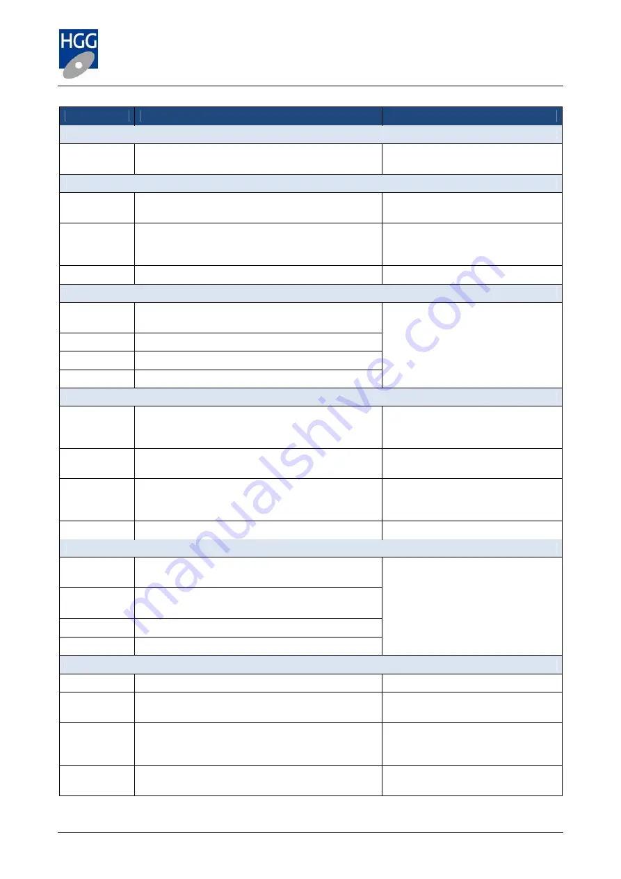
Error number 

Error text 

Problem/Reference chapter 

Staubli robot 

003:010:029 

Error sending Staubli Arc control 

Move robot to safe, this will re-send 
the Arc control data 

Plasma tool ignition 

003:012:301 

Plasma pilot/main arc timeout 

Check the nozzle, clean if 
necessary and try again. 

003:012:302 

Plasma main arc timeout after pilot arc 

Check the plasma unit for an error. 
Check the nozzle, clean if 
necessary. 

003:012:303 

Plasma unit error during ignite 

Check the plasma unit for an error. 

Data collector 

003:025:001 

Data Collector returned no result. Data not 
collected. 

The data collector keeps a record of 
machine activity. Messages marked 
with * are notifications not errors. 
For the remaining messages, check 
the path (file location). 

003:025:002 

Purging archive ... (older than <number> days)* 

003:025:003 Purged 

archive* 

003:025:005 

Data Collector, settings loaded* 

ProCAM 

005:002:006 

Error starting ProCAM 

First check the path the try again. 
The default path is C:\Program 
Files\HGG\ProCAM 

005:002:008 License not found 

Insert your HASP key (see ProCAM 
manual for further help) 

005:002:009 

License lost, shutting down after <number> 
seconds 

Insert key. If the key is inserted, 
check the connection, remove and 
replace the key. 

005:002:010 License 

restored 

Notification. 

REA inkjet printer controller 

005:062:001 

Error communicating with printer on port 
<numbered port> 

Check the printer connection and try 
again. If the problem continues, 
contact HGG 

005:062:002 

Error sending purge command, communication 
error 

005:062:003 

Error sending text to printer 

005:062:004 

Error sending line to printer 

Settings 

009:001:001 

Unable to open settings file: <named file> 

Check the path and the file name. 

009:001:002 

File <named file> does not exist. Do you want to 
create this file? 

File not found, check path. If it is a 
new setting, create the file. 

009:001:003 

Unable to create settings file: <named file> 

There is a security block on some 
essential files, these files may not 
be changed. 

009:001:004 

Name change not allowed 

The name of this setting may not be 
changed. 


Summary of Contents for PCL 600

Page 1: ...Profile Cutting Line Operators Manual Official manual of the Profile Cutting Line Includes types PCL 600...

Page 2: ...s is the operator s manual for the PCL 600 profile cutting line For any questions or comments please contact Manufacturer HGG Profiling Equipment b v Address Zuidrak 2 1771 SW Wieringerwerf Country Th...

Page 3: ...plasma unit ProCAM Manual Framework and ProGRAM Contains instructions and description of the ProCAM software including programming instructions and nesting Course Book ProCAM Framework Course book for...

Page 4: ...LABELS 13 2 6 EMERGENCY STOP 14 3 MACHINE DESCRIPTION 15 3 1 LAY OUT PCL 600 15 3 2 MACHINE COMPONENTS 16 4 CONTROLS 18 4 1 MACHINE CONTROLLER 18 4 2 ROBOT CONTROLLER 18 4 3 USING THE TOUCH SCREEN CON...

Page 5: ...OOLCALMID CALIBRATION PIECE 46 8 4 3 ENTER THE CALIBRATE TOOL MEASUREMENTS 47 8 5 CUTTING COMPENSATION 48 8 5 1 PROFILE SELECTION 48 8 5 2 SHIFT DIRECTION 48 8 5 3 ADJUSTMENTS 48 9 CUTTING TABLES 49 9...

Page 6: ...PCL 600 Operators Manual v 2 0 6 10 2 9 PLASMA UNIT 56 10 3 SMALLER COMPONENTS 56 APPENDIX A TERMINOLOGY 57 APPENDIX B NOTIFICATIONS WARNINGS AND ERRORS 58 APPENDIX C CE CERTIFICATE 69...

Page 7: ...gth Maximum length Raw bar 5 mm 60 mm 2 500 kg 2000 mm 12000 mm Cutting process Minimum wall thickness Maximum wall thickness Cutting angle range Plasma 5 mm 60 mm 35 mm quality cut 45 to 45 1 3 Mater...

Page 8: ...imum noise level measured at a distance of 1 meter 3 meter No load 70 dB A Pilot arc 24 Amp 96 dB A 88 dB A 250 Amps 10 mm 103 dB A 93 dB A 250 Amps 40 mm 105 dB A 99 dB A Source Kjellberg Finsterwald...

Page 9: ...er is a person or organisation who is responsible for the machine Authorised person An authorised person is someone who is authorised by the user to carry out certain activities on the machine Skilled...

Page 10: ...er 2 of this manual Safety have sufficient knowledge to carry out the activities on the machine have knowledge of the presence and working of the emergency stop mechanism of the machine have knowledge...

Page 11: ...chine All fixed guards are in place Some can be removed for cleaning lubrication and maintenance The machine is free of jams and other obstacles Furthermore Never leave the machine stopped in such a m...

Page 12: ...asma cutting process generates high temperatures Material may be hot for a time after cutting There is a safety switch on the doors to the cutting cell cutting cannot take place if the doors are open...

Page 13: ...nt side of the remote control Read and understand operator s manual before operating this machine Front side of the remote control Warning Moving parts Operator s side of the sideways infeed Side of t...

Page 14: ...e remote control The following procedure must be followed to restart the machine after an emergency stop 1 MAKE SURE THAT IT IS SAFE TO OPERATE THE MACHINE AGAIN 2 Pull out the emergency stop button o...

Page 15: ...pable of cutting a wide range of profiles including flat bars bulbs equal and unequal angle bars and T bars 3 1 Lay out PCL 600 1 Gripper 7 Printer inkjet 13 Slatted outfeed belt pusher 2 Main frame g...

Page 16: ...terial on the sideways loading chains In the same way the outfeed buffer chains can be raised lifting finished parts from the outfeed conveyor and moving them onto the buffer chains ready to be unload...

Page 17: ...mergency stop pull cord Outfeed roller conveyor Larger parts are transported to the driven outfeed roller conveyor When the part is in position it can be transported further depending on the logistic...

Page 18: ...l panel which is situated on a flexible arm attached to the cutting cell giving the operator a good view of the whole process 4 2 Robot controller Operating instructions for the CS8 robot controller a...

Page 19: ...When the air pressure is correct the light will come on Robot slow Slows all robot arm movement except for during cutting When the plasma service button is pressed slow movement is automatically activ...

Page 20: ...sh the button again to proceed to the next cut marking NOTE the stainless steel Play button under the touch screen can also be used Push material to cell The gripper moves along the rail toward the ce...

Page 21: ...h to mark press here to disable Top printer up down Profiling mode Cutting cell These buttons control the clamps the robot arm and the movement of material in or through the cutting cell The cutting c...

Page 22: ...tomatic outfeed This button restarts an automatic outfeed action that was interrupted or not completed Calibration mode Homing The machine components in this section must be moved to their home positi...

Page 23: ...ration mode Sideways infeed Move sideways loading chains towards gripper Move sideways loading chains away from gripper Calibration mode Gripper Move gripper left Move gripper right Calibration mode C...

Page 24: ...ial specifications Contains details about the material the current data file and the progress Auto Cut List Shows list of the data files to be profiled Files can be added to or removed from the list t...

Page 25: ...emote control Turn the air supply on and make sure it is at the correct pressure Turn the CS8 robot controller on The controller is located in the middle section of the blue control unit cabinet mount...

Page 26: ...his manner will appear in the auto cut list as a single temporary file with a default name Manually selected files are loaded and cut directly whereas when adding files to the auto cut list using the...

Page 27: ...gned a status or removed from the list The status refers to the location of the raw material in the process The order in which the files are processed depends on their location on the machine and not...

Page 28: ...e The material is at the storage station Edge cleaning The material is being brushed or shot blasted in the edge cleaning unit option Storage2 The material is on the infeed buffer chains Loading table...

Page 29: ...nfeed gripper clamps and printers as described earlier in this manual The buttons in the Cutting section of the Cutting window of the touch screen will flash to let the operator know that the machine...

Page 30: ...ng menu in the menu bar at the top of your screen When you have selected a file press Start Cutting 5 Initialise Once the file has been loaded press Initialise The machine uses this reference position...

Page 31: ...ction Graphic from the selection button in the information section of the touch screen This shows information about the current file being processed in the table and the window underneath shows a grap...

Page 32: ...lly be removed from the cell to the outfeed The data file contains information regarding the length of each individual part Parts between 300 and 4000 mm will be pushed from the outfeed slat belt to t...

Page 33: ...ding up to the problem Click on the Collect button to save the information Wait until the information has been collected The window will display the word Collected and show a green light and the locat...

Page 34: ...ip correction Auto hold Check this box to automatically stop the outfeed belt if the deviation due to slip becomes too much Enable Activate the slip correction This feature compensates for material sl...

Page 35: ...istance between retries Scrap removal Enter the scrap removal distance Tool Cutting Current tool If your machine is equipped for oxyfuel cutting choose between plasma and oxyfuel LowerFlangeFirst Make...

Page 36: ...a short description of the problem and the events leading up to it This will be saved to the Archive folder and can provide useful information for the service engineers 7 5 3 Print last cut parts A li...

Page 37: ...the boxes and click on Replaced The information is then updated in the window 7 6 1 Maintenance and Data Monitors These are diagnostic dialogs for the HGG service engineers The maintenance monitor giv...

Page 38: ...r the first two of these procedures For the plasma torch calibration you will need a flat bar that complies with the following conditions Web size 200 to 300 mm Thickness 10 to 30 mm Maximum deflectio...

Page 39: ...ll are clean and moving smoothly Check that the compressed air pressure is correct Select the Calibration screen on the remote control Activate the robot high power Disable the safety lock Home the gr...

Page 40: ...led It is usually only necessary to repeat the procedure if there is a problem or a collision has occurred To calibrate the active frame you will need the calibration column a short piece of raw mater...

Page 41: ...ial into the cell during calibration Gear the gripper again 6 On the remote control press the Gas off button to turn off the plasma the torch will still make all the movements to cut the data file but...

Page 42: ...OP surface is determined by the orientation of all profiles in the cutting cell which will always be the same The Top will always be next to the short stroke horizontal clamps The measurement of the d...

Page 43: ...e refer to the ProCAM manual if you need help Open a new file in the File menu top left 3 ProCAM will automatically create a new project assembly and part If you have not entered a default profile in...

Page 44: ...ype field and select Plasma The result should now look like the example shown here below 11 The gold stars indicate that the file has not yet been saved Save the file now by selecting the file in the...

Page 45: ...d because the smaller the square the more difficult it is to measure and the less accurate the measurement In the example below the square has been moved closer to the end by reducing the value of the...

Page 46: ...ation of the material right click on the file name in the auto cut list The Status menu will open The material is on the infeed conveyor this location is Machine in the status menu see image right 6 Y...

Page 47: ...the fields provided Press Ok to enter the values the torch dimensions are automatically calculated and entered for you This completes the tool calibration This process should be repeated regularly to...

Page 48: ...t HGG for more information 8 5 1 Profile selection In the drop down menu at the top right of the dialog you can choose the profile for which you wish to enter compensation corrections see image below...

Page 49: ...ting table and their influence on the final results 9 1 Editing the cutting table To edit the cutting table first open the Cutting settings from the Service menu at the top of your screen or using the...

Page 50: ...he cutting beam By entering the correct kerf width the machine can compensate for the thickness of the beam by offsetting the torch by half the kerf width so that the cut is precisely on the cut line...

Page 51: ...entered in millimetres positive longer negative shorter The offset is adjusted linearly from 100 at a 45 bevel down to 0 at no bevel Ignition height The distance between the torch and material at the...

Page 52: ...re painted or coated to prevent rusting However some parts are exposed to the air and should be oiled or greased regularly for protection Alternatively spray the parts with oil and seal with plastic c...

Page 53: ...e bolts holding the support legs to the floor Stack the beams and support legs on pallets place wooden planks between the beams to prevent damage Secure firmly before transporting to storage 10 2 2 Ou...

Page 54: ...ace wooden planks in between them to stabilise and support and prevent damage Before storing make sure the chains are lubricated Once in storage check the condition of the chains at regular intervals...

Page 55: ...aps Close and lock all the doors There are four lifting hooks situated on the top of the cutting cell it is important that all four are used when lifting to keep the cell in balance Always lift a smal...

Page 56: ...of the unit must be used If placed on a pallet the wheels should be boxed in or the unit prevented from rolling by another means Weight 300 kg The flow control unit can be removed for storage For more...

Page 57: ...ity of the cut it is better to pierce at a short distance from the cut This distance is referred to as lead in Similarly when the cut has been completed the torch shuts down this can also affect the q...

Page 58: ...r on Pmac motor named Check the named amplifier 003 000 003 Open loop error on Pmac motor named The motor is not in closed loop mode The CNC controller is unable to control the motor 003 000 005 Error...

Page 59: ...not cannot gather 24 bit addresses 48 bit address starts with 4 or C 003 000 034 Pmac error aborting gather 003 000 035 Invalid Pmac motor speed count received named 003 000 036 Home offset named out...

Page 60: ...ill running Wait for the current calculation to be completed try again Disable the macro calculator in the settings Enable and try again Staubli robot 003 010 009 CMND error Error sending command to r...

Page 61: ...irst check the path the try again The default path is C Program Files HGG ProCAM 005 002 008 License not found Insert your HASP key see ProCAM manual for further help 005 002 009 License lost shutting...

Page 62: ...out this action 014 003 017 Robot not in high power Activate robot high power 014 003 018 Air pressure too low Check pressure Check the air pressure 014 003 020 Unable to turn on power robot in servi...

Page 63: ...Pusher in synchro mode no action allowed You cannot perform a home action when the gripper is still geared Ungear the gripper 014 016 037 Track Calibrate error end switch not reached Check if the gri...

Page 64: ...printer switch Check if there was a dip in air pressure 014 016 096 Error gripping material Material between infeed light crossing The infeed sensor is blocked Remove material from blocking the infeed...

Page 65: ...ot feed in material material already at sensor on infeed table or one of the sensors is damaged Is there already material on the track Remove it Is the infeed sensor is blocked dirty damaged Clear the...

Page 66: ...pressure Try again 014 025 504 Timeout in sending print head to home position 014 025 702 Timeout moving under printer to material Cutting cell doors 014 027 100 Cell doors unlock took too long skipp...

Page 67: ...les 014 033 005 Could not open cutting table named file Check the settings to see if the file exists and that the spelling is correct Check if you have permission to access this folder Outfeed pusher...

Page 68: ...ains try again 014 041 202 Infeed storage cannot be moved while placing is in progress Finish loading before moving the infeed buffer chains 014 041 203 Infeed storage placing not completed Tables not...

Page 69: ...s 133013 133113 133213 133313 133413 which this declaration refers to are in accordance with the conditions of the following Directive s 2006 42 EG 2004 108 EG and are in conformity with the following...

Reviews: