EPS 45-80 High-Voltage Generator
3-36
Technical Manual P/N 9894.00.G6
3.6.4
SPD Dose Tracking Interface (Optional Feature)
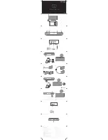
The Source to Patient Distance (SPD) can be tracked during Fluoro to maintain the Fluoro surface
dose when the tube or the image amplifier moves. The distance is tracked using an analog signal
inputted at J14- pin 10, which ranges from 0.1 to 10 V
DC
(Figure 3.17).
Figure 3.17
–
Typical SPD Input Interfacing Diagram.
3.7
FLUORO INTERFACE
3.7.1
Image Intensifier Pickup Device
Fluoro signals are interfaced on Fluoro PMT board P/N 9822.00 or on Photodiode Ion Chamber
Fluoro board P/N 11030.000 (Figures 3.18 & 3.19).
1.
Connect the feedback signal (RG-59/U coaxial) :
a.
From a phototube: To J5 BNC-connector on the Fluoro PMT board.
Gain can be varied from about -200 V to about -950 V.
b.
From a photodiode: To J6 BNC-connector on the Fluoro PhD board.
Usable input signal range:
−
Continuous Fluoro:
from ~ 5mV to 1V or from ~ -5mV to -1V
−
Pulsed Fluoro & AEC: from ~ 12.5mV to 9V or ~ -12.5mV to -9V
NOTE:
On
Photodiode Ion Chamber Fluoro board P/N 11030.000
, two gain levels are
available to interface the photodiode. Use J10 connector
to select the proper gain level:
Jumper in position 1-2: Normal gain for photodiode
Jumper in position 2-3: Low gain for photodiode (Slow ramp ABS)
2.
For a phototube device, connect the high voltage supply of the phototube (RG-59/U coaxial) to
J1 BNC-connector on the Fluoro PMT board.
3.
Refer to :
−
Section 3.6.4 to interface SPD option, if fitted on the generator.
−
Section 5.4 to adjust the Fluoro maximum surface dose.
−
Section 5.5 to adjust the Fluoro stabilization dose.