


6-4
SECTION 6 –
ELECTRICAL SYSTEMS
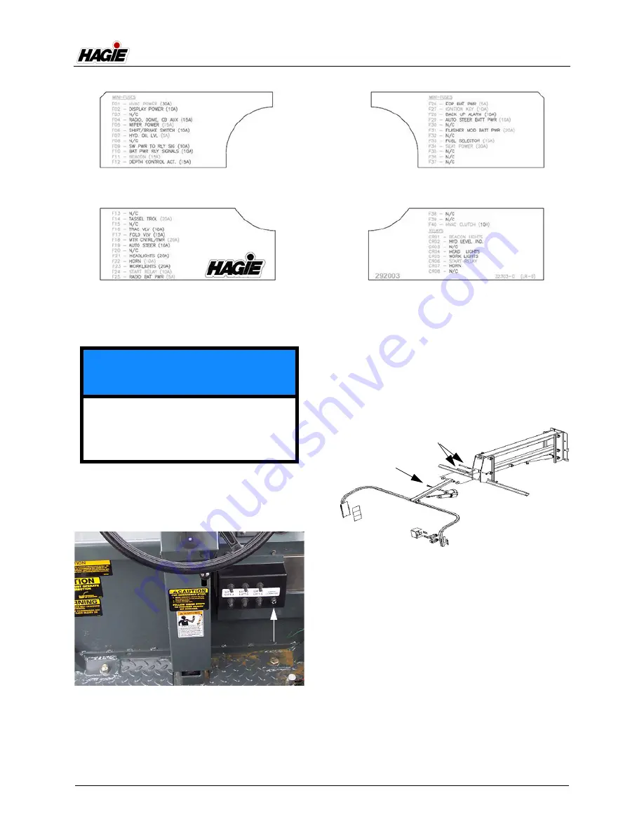
Depth Command Fuse
-If Equipped
The Depth Command Fuse is located on
the Depth Command Switch Panel (located
near the front of operator’s station).
NOTE: A blown fuse may indicate that the
LS/Depth Command Pivot Bolts (as
shown in the following illustration)
are torqued too tight. If the fuse
continues to blow, determine the
cause and correct. Contact your
John Deere dealer if additional
assistance is needed.
Wire Harness Circuit Breaker
and Fuses
The Wire Harness Circuit Breaker and
Fuses (located on the right-hand side of
engine) protect the cab wiring, alternator,
and grid heater.
NOTICE
Do not operate more than two (2)
actuators at one time. Failure to comply
may result in blowing the depth
command fuse.
Depth Command Fuse
(Located on the Depth Command Switch
Panel near front of operator’s station)
-Typical View
LS/Depth Command Pivot Bolts
-Typical View
Summary of Contents for 204SP
Page 2: ...5 DASH AUTO...
Page 127: ......