


1-15-96
96-8100
HAAS
AUTOMATION, INC.
69
MECHANICAL SERVICE
S E R V I C E M A N U A L
VF-S
ERIES
1/8" x 1" cotter pin.
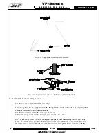
C. Attach the winch base to the boom with the two 3/8-16x1" SHCS, two 3/8" lock washers, and
the two 3/8" hex nuts. See owner's manual for mounting for left-or right-handed operation.
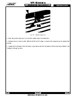
D. Feed the free end of the cable (without hook) between the pulley and cable guide and
through the inside of the boom.
Fig. 8-4 Mounting cable guide and pulley wheel to boom.
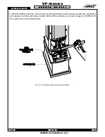
E. Attach the cable to the winch as follows:
1) FOR LEFT-HAND OPERATION -
Pass the cable under the winch drum and through the hole in the drum flange.
Form a loop of cable and securely anchor it in place using the tie-down clasp, carriage
bolt, and hex nut. The cable must be underwound on the winch drum.
2) FOR RIGHT-HAND OPERATION -
Pass the cable between the frame rod and the countershaft of the winch, over the
winch drum, and through the hole in the drum flange. Form a loop of cable and
securely anchor it in place using the tie-down clasp, carriage bolt, and hex nut.
The cable must be overwound on the winch drum.
F. Ensure all hex nuts and cap nuts are securely tightened and all cotter pins are properly bent
to secure them in place. Make sure all pivots and rotation points are well-lubricated and refer to
the winch owner's manual for proper lubrication before operating.
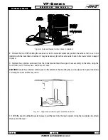
4. Place the transmission lift fixture on top of the transmission, with the rod at each end in the two lifting eyeholes of
the transmission. Tighten the fixture onto the transmission by turning the handle at the end.
NOTE:
Do not over-
tighten.
Summary of Contents for VF-SERIES
Page 180: ...1 15 96 96 8100 177 TABLEOFCONTENTS TECHNICAL REFERENCE SERVICE M A N U A L VF SERIES ...
Page 235: ...96 8100 1 15 96 232 VF SERIES S E R V I C E M A N U A L ASSEMBLY DRAWINGS VF 1 COLUMN ...
Page 237: ...96 8100 1 15 96 234 VF SERIES S E R V I C E M A N U A L ASSEMBLY DRAWINGS VF 1 LEADSCREW ...
Page 239: ...96 8100 1 15 96 236 VF SERIES S E R V I C E M A N U A L ASSEMBLY DRAWINGS VF 3 COLUMN ...
Page 241: ...96 8100 1 15 96 238 VF SERIES S E R V I C E M A N U A L ASSEMBLY DRAWINGS VF 3 LEADSCREW ...
Page 245: ...96 8100 1 15 96 242 VF SERIES S E R V I C E M A N U A L ASSEMBLY DRAWINGS 3 4 2 1 ...


