


1-15-96
96-8100
HAAS
AUTOMATION, INC.
57
MECHANICAL SERVICE
S E R V I C E M A N U A L
VF-S
ERIES
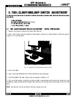
5. TOOL CLAMP/UNCLAMP SWITCH ADJUSTMENT
PLEASE READ THIS SECTION IN ITS ENTIRETY BEFORE ADJUSTING CLAMP/UNCLAMP SWITCHES OR SETTING DRAW-
BAR HEIGHT.
TOOLS REQUIRED:
MACHINED ALUMINUM BLOCK (2" x 4" x 4")
6" FLEXIBLE RULER or .020" SHIM
1" DIA. PIPE (APPROX. 1' LONG)
5.1 TOOL CLAMP/UNCLAMP SWITCH ADJUSTMENT - INITIAL PREPARATION
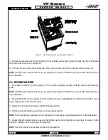
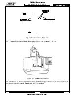
1. Remove cover panels, as described in "Head Covers Removal".
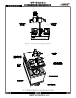
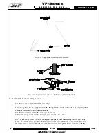
2. Place a sheet of paper under the spindle for table protection, then place a machined block of aluminum (approxi-
mately 2" x 4" x 4") on the paper.
Fig. 5-1 Placement of aluminum block under spindle.
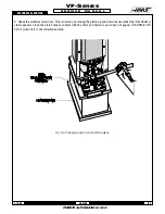
3. Power on the VMC.
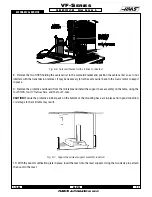
4. Insert a tool holder WITHOUT ANY TYPE OF CUTTER into the spindle taper.
5. Go to the HANDLE JOG mode. Choose Z-axis and set jog increments to .01.
6. Jog Z-axis in the negative (-) direction until the tool holder is approximately .03 from the block. At this point, stop
jogging the spindle and push the tool release button (top left). You will notice that the tool holder comes out of the
taper.
NOTE:
The clearance from the tool holder to the block should be zero (0).
Summary of Contents for VF-SERIES
Page 180: ...1 15 96 96 8100 177 TABLEOFCONTENTS TECHNICAL REFERENCE SERVICE M A N U A L VF SERIES ...
Page 235: ...96 8100 1 15 96 232 VF SERIES S E R V I C E M A N U A L ASSEMBLY DRAWINGS VF 1 COLUMN ...
Page 237: ...96 8100 1 15 96 234 VF SERIES S E R V I C E M A N U A L ASSEMBLY DRAWINGS VF 1 LEADSCREW ...
Page 239: ...96 8100 1 15 96 236 VF SERIES S E R V I C E M A N U A L ASSEMBLY DRAWINGS VF 3 COLUMN ...
Page 241: ...96 8100 1 15 96 238 VF SERIES S E R V I C E M A N U A L ASSEMBLY DRAWINGS VF 3 LEADSCREW ...
Page 245: ...96 8100 1 15 96 242 VF SERIES S E R V I C E M A N U A L ASSEMBLY DRAWINGS 3 4 2 1 ...


