


96-8100
1-15-96
166
TECHNICAL REFERENCE
S E R V I C E M A N U A L
VF-S
ERIES
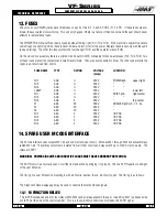
11.4 POWER PCB (POWER)
The low voltage power distribution and high voltage fuses and circuit breakers are mounted on a circuit board called the
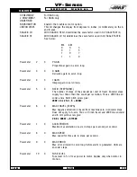
POWER PCB. The following connectors are on it:
P1
Five-pin brings 230V AC three ph from main breaker
P2
On/Off connections to front panel (740)
P3
Coil and aux connections to contactor K1
P4
Auto-off connection to IOPCB (170)
P5
Low voltage control transformer to power K1
P6
230V AC from CB3 to coolant pump (930)
P7
115V AC from CB4 to IOPCB for solenoids (910)
P8
115V AC /T1 (90)
P9
Tool changer fuse circuit from FU5 to IOPCB (840)
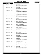
P10
+5/+12/Gnd form low volt supply to logic boards (860)
P11
+5/+12/Gnd form low volt supply to logic boards (860)
P12
+5/+12/Gnd form low volt supply to logic boards (860)
P13
+5/+12/Gnd form low volt supply to logic boards (860)
P14
12V AC to operators lamp (800A)
P15
230V AC from contactor K1 for coolant pump (70)
P16
Low voltage power from power supply
P17
+12V DC to IOPCB (860A)
P18
Not used
P19
Connector to op. lamp transformer T4 (290)
P20
115V AC to low voltage supply
P21
-12V DC to processor PCB
P22
-12V DC to MOTIF PCB
P26
+12V DC option connector
P27
+5/+12/Gnd form low volt supply to logic boards (860)
P30
12V AC OP Lamp (800)
P31
+12V (860A)
For older internal transformer with 208/230 taps:
TB1
230V AC from contactor K1
TB2
230V AC to T1 primary
11.5 POWER-UP LOW VOLTAGE CONTROL TRANSFORMER (T5)
The low voltage control transformer, T5, supplies power to the coil of the main contactor K1. It guarantees that the maximum
voltage leaving the Power Supply assembly when power is off is 12V AC to earth ground. It is connected via P5 to the
POWER PCB.
11.6 SECONDARY CIRCUIT BREAKERS
Three more circuit breakers are on the Power supply assembly.
CB2
controls the 115volt power from the main transformer to the servo transformers and, if tripped, will turn off the servo
motors and air solenoids. CB2 could be blown by a severe servo overload.
Summary of Contents for VF-SERIES
Page 180: ...1 15 96 96 8100 177 TABLEOFCONTENTS TECHNICAL REFERENCE SERVICE M A N U A L VF SERIES ...
Page 235: ...96 8100 1 15 96 232 VF SERIES S E R V I C E M A N U A L ASSEMBLY DRAWINGS VF 1 COLUMN ...
Page 237: ...96 8100 1 15 96 234 VF SERIES S E R V I C E M A N U A L ASSEMBLY DRAWINGS VF 1 LEADSCREW ...
Page 239: ...96 8100 1 15 96 236 VF SERIES S E R V I C E M A N U A L ASSEMBLY DRAWINGS VF 3 COLUMN ...
Page 241: ...96 8100 1 15 96 238 VF SERIES S E R V I C E M A N U A L ASSEMBLY DRAWINGS VF 3 LEADSCREW ...
Page 245: ...96 8100 1 15 96 242 VF SERIES S E R V I C E M A N U A L ASSEMBLY DRAWINGS 3 4 2 1 ...


