


96-8100
1-15-96
54
MECHANICAL SERVICE
HAAS
AUTOMATION, INC.
S E R V I C E M A N U A L
VF-S
ERIES
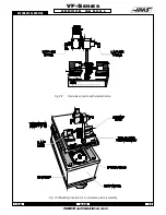
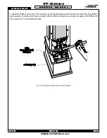
7. Fill the cavity between the housing and the spindle cartridge with oil. The oil fill hole is to the left side of the spindle
head near the spindle bore, as viewed from the top.
WARNING!
Never pour oil into the spindle housing.
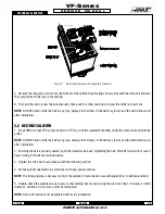
8. Reinstall the drive belt and adjust the tension as needed.
9. Reinstall the tool release piston assembly.
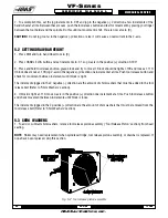
10. Check the spindle sweep, as described later in this section.
NOTE:
Refer to the appropriate sections and check the spindle orientation and ATC alignment.
4.3 DRAWBAR REPLACEMENT
NOTE:
If machine is equipped with the TSC option, refer to the "Through the Spindle Coolant" section for the drawbar
replacement procedure.
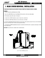
REMOVAL -
1. Place a tool holder with no cutter in the spindle.
2. Remove head cover panels as shown in "Head Covers Removal'.
3. Remove the tool release piston in accordance with appropriate section.
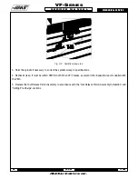
4. Remove the snap ring from the top of the spindle shaft.
5. Reinstall the tool release piston.
6. Remove the tool holder from the spindle.
7. Remove the spindle, as described earlier in this section.
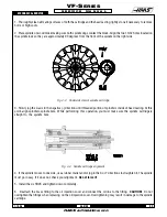
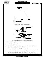
8. Remove the drawbar and distance tube from the spindle assembly.
INSTALLATION -
9. Thoroughly coat the replacement drawbar with grease, including the end of the shaft where the four holding balls
are located.
10. If machine is equipped with Through the Spindle Coolant option, grease the O-rings.
11. Insert four new balls in the replacement drawbar and insert into the spindle shaft. Be sure that as the shaft is
installed, the balls do not fall out of the bores in the drawbar.
CAUTION!
Insert the drawbar gently so the O-rings are not damaged. DO NOT use a hammer to force it.
NOTE:
Carefully inspect the spindle shaft for galling or burrs inside the spindle shaft where the end of the drawbar
rides. If it is damaged, the spindle must be replaced.
Summary of Contents for VF-SERIES
Page 180: ...1 15 96 96 8100 177 TABLEOFCONTENTS TECHNICAL REFERENCE SERVICE M A N U A L VF SERIES ...
Page 235: ...96 8100 1 15 96 232 VF SERIES S E R V I C E M A N U A L ASSEMBLY DRAWINGS VF 1 COLUMN ...
Page 237: ...96 8100 1 15 96 234 VF SERIES S E R V I C E M A N U A L ASSEMBLY DRAWINGS VF 1 LEADSCREW ...
Page 239: ...96 8100 1 15 96 236 VF SERIES S E R V I C E M A N U A L ASSEMBLY DRAWINGS VF 3 COLUMN ...
Page 241: ...96 8100 1 15 96 238 VF SERIES S E R V I C E M A N U A L ASSEMBLY DRAWINGS VF 3 LEADSCREW ...
Page 245: ...96 8100 1 15 96 242 VF SERIES S E R V I C E M A N U A L ASSEMBLY DRAWINGS 3 4 2 1 ...