


1-15-96
96-8100
HAAS
AUTOMATION, INC.
67
MECHANICAL SERVICE
S E R V I C E M A N U A L
VF-S
ERIES
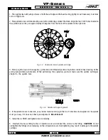
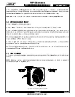
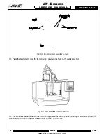
Figure 8-1 VF-0 with lifting eyeholes.
8.2 INSTALLATION (VF-0)
1. Carefully lower the motor assembly down to just above the spindle head casting, taking care not to damage the drive
pulley or pinch the drive belt.
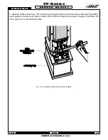
2. Place the drive belt on the motor's drive pulley and lower the motor down onto the spindle head casting.
3. Insert and tighten down the four SHCS attaching the motor to the spindle head casting. Adjust the drive belt as noted
in "Belt Assembly" before tightening down completely.
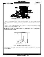
4. Refer to the appropriate section and set the spindle orientation.
5. Check for proper orientation of the machine and be aware of any unusual noises or vibration that may occur because
of incorrect belt tension.
6. Reattach the cable carrier to the solenoid bracket and reconnect all electrical and fluid lines. Replace any leaking or
damaged lines at this time, if necessary.
NOTE:
Ensure the orient ring has an adequate layer of grease around the circumference before starting operation.
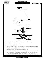
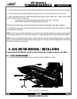
8.3 HOIST PRE-ASSEMBLY
1. Attach the mast support to the support base, using the four 3/8-16 x 1¼" SHCS, four 3/8" flat washers, four split
washers, and the four 3/8-16 hex nuts. Ensure the bolts are securely tightened.
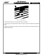
2. Attach the boom modification plates to the mast using the three ½-13 x 4½" HHB, three ½" split washers, three ½-
13 hex nuts, and the three spacers.
Summary of Contents for VF-SERIES
Page 180: ...1 15 96 96 8100 177 TABLEOFCONTENTS TECHNICAL REFERENCE SERVICE M A N U A L VF SERIES ...
Page 235: ...96 8100 1 15 96 232 VF SERIES S E R V I C E M A N U A L ASSEMBLY DRAWINGS VF 1 COLUMN ...
Page 237: ...96 8100 1 15 96 234 VF SERIES S E R V I C E M A N U A L ASSEMBLY DRAWINGS VF 1 LEADSCREW ...
Page 239: ...96 8100 1 15 96 236 VF SERIES S E R V I C E M A N U A L ASSEMBLY DRAWINGS VF 3 COLUMN ...
Page 241: ...96 8100 1 15 96 238 VF SERIES S E R V I C E M A N U A L ASSEMBLY DRAWINGS VF 3 LEADSCREW ...
Page 245: ...96 8100 1 15 96 242 VF SERIES S E R V I C E M A N U A L ASSEMBLY DRAWINGS 3 4 2 1 ...


