1-15-96
96-8100
HAAS
AUTOMATION, INC.
35
TABLE OF CONTENTS
ALARMS
S E R V I C E M A N U A L
VF-S
ERIES
352
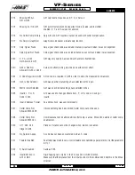
Aux Axis Power Off
Aux
B
,
C
,
U
,
V
, or
W
axis indicate servo off. Check auxiliary axes. Status from control was OFF.
353
Aux Axis No HomeA ZERO RET has not been done yet on the aux axes. Check auxiliary axes. Status from control
was LOSS.
354
Aux Axis
Aux axes not responding. Check auxiliary axes and RS-232 connections.
Disconnected
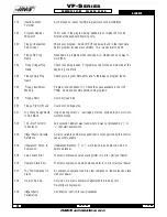
355
Aux Axis
Position Mismatch between machine and aux axes position. Check aux axes and
Mismatch
interfaces. Make sure no manual inputs occur to aux axes.
356
Aux Axis Travel Limit
Aux axes are attempting to travel past their limits.
357
Aux Axis Disabled Aux axes are disabled.
358
Multiple Aux Axis
Can only move one auxiliary axis at a time.
359
Invalid I, J, or K In G12
Check your geometry with the HELP page.
or G13
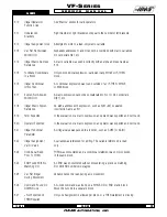
360
Tool Changer Disabled
Check Parameter 57. Not a normal condition for VF Series CNC Mill.
361
Gear Change Disabled
Check Parameter 57. Not a normal condition for VF Series CNC Mill.
362
Tool Usage Alarm
Tool life limit was reached. To continue, reset the usage count in the Current Commands
display and press RESET.
363
Coolant Locked Off
Override is off and program tried to turn on coolant.
364
No Circ Interp
Only rapid or feed is allowed with aux axes.
Aux Axis
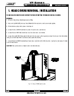
367
Cutter Comp
G01 cannot be done with tool size.
Interference
368
Groove Too Small
Tool too big to enter cut.
369
Tool Too Big
Use a smaller tool for cut.
370
Pocket Definition
Check geometry for G150.
Error
371
Invalid I, J, K, OR Q
Check G150.
372
Tool Change In
Tool change not allowed while canned cycle is active.
Canned Cycle
373
Invalid Code in DNC
A code found in a DNC program could not be interpreted because of
restrictions to DNC.
Summary of Contents for VF-SERIES
Page 180: ...1 15 96 96 8100 177 TABLEOFCONTENTS TECHNICAL REFERENCE SERVICE M A N U A L VF SERIES ...
Page 235: ...96 8100 1 15 96 232 VF SERIES S E R V I C E M A N U A L ASSEMBLY DRAWINGS VF 1 COLUMN ...
Page 237: ...96 8100 1 15 96 234 VF SERIES S E R V I C E M A N U A L ASSEMBLY DRAWINGS VF 1 LEADSCREW ...
Page 239: ...96 8100 1 15 96 236 VF SERIES S E R V I C E M A N U A L ASSEMBLY DRAWINGS VF 3 COLUMN ...
Page 241: ...96 8100 1 15 96 238 VF SERIES S E R V I C E M A N U A L ASSEMBLY DRAWINGS VF 3 LEADSCREW ...
Page 245: ...96 8100 1 15 96 242 VF SERIES S E R V I C E M A N U A L ASSEMBLY DRAWINGS 3 4 2 1 ...


