


81
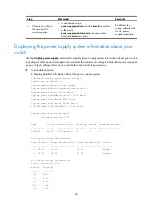
To verify transceiver modules:
Task Command
Display key parameters of the transceiver in a
specified interface
display transceiver interface
[
interface-type
interface-number
]
Display part of the electrical label information of
transceiver in a specified interface
display transceiver manuinfo interface
[
interface-type
interface-number
]
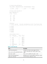
# Display the main parameters of the transceiver plugged in interface GigabitEthernet 3/0/19.
<Sysname> display transceiver interface gigabitethernet 3/0/19
GigabitEthernet3/0/19 transceiver information:
Transceiver Type : 1000_BASE_SX_SFP
Connector Type : LC
Wavelength(nm) : 850
Transfer Distance(m) : 550(50um),270(62.5um)
Digital Diagnostic Monitoring : YES
Vendor Name : H3C
Ordering Name : SFP-GE-SX-MM850
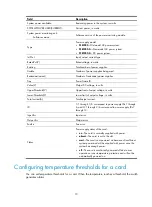
Table 22
Command output
Field Description
transceiver information
Transceiver information
Transceiver Type
Transceiver type
Connector Type
Type of the connectors of the transceiver:
•
SC
—Fiber connector, developed by NTT
•
LC
—1.25 mm/RJ-45 optical connector developed by Lucent.
•
RJ-45
•
CX 4
Wavelength(nm)
•
Fiber transceiver
—Central wavelength (in nm) of the laser sent. If the
transceiver module supports multiple wavelengths, every two wavelength
values are separated by a comma.
•
Copper cable
—Displayed as N/A.
Transfer distance(xx)
Transfer distance, where "xx" represents the distance unit: km (kilometers) for
single-mode transceivers and m (meters) for other transceivers.
If the transceiver supports multiple transfer medium, every two values of the
transfer distance are separated by a comma. The transfer medium is included in
the bracket following the transfer distance value. The following are the transfer
media:
•
9 um
—9/125
μ
m single-mode optical fiber
•
50 um
—50/125
μ
m multi-mode optical fiber
•
62.5 um
—62.5/125
μ
m multi-mode optical fiber
•
TP
—Twisted pair
•
CX4
—CX4 cable
Digital Diagnostic
Monitoring
Support for the digital diagnosis function:
•
YES
—Supported
•
NO
—Not supported
Summary of Contents for S12500 Series
Page 40: ...30 Figure 28 Installing an upper expansion cable management bracket 1 2 3 4 5 6 7...
Page 109: ...99 Figure 74 Replacing a card for the S12504 A Card to be removed B Card to be installed...
Page 149: ...139 Figure 85 Loopback operation on an optical transceiver...
Page 164: ...154 Figure 100 Example of a device label...


