


3
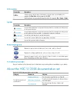
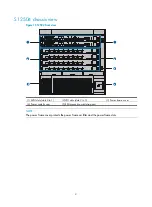
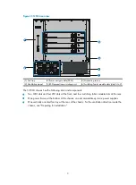
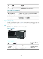
Figure 2
S12504 rear view
(1) Fan tray
(2) Power entry module (PEM)
(3) Grounding screw
(4) Ventilation panel
(5) ESD-preventive wrist strap port
(6) Switching fabric module slots (slots 6 to 9)
The S12504 chassis has the following slots and components:
•
Two MPU slots and four LPU slots at the front, and four switching fabric module slots at the rear.
•
One power frame, at the bottom of the chassis, can accommodate up to six power supplies.
•
One vertically oriented fan tray at the rear of the chassis. For the ventilation direction inside the
chassis, see "Preparing for installation."
Summary of Contents for S12500 Series
Page 40: ...30 Figure 28 Installing an upper expansion cable management bracket 1 2 3 4 5 6 7...
Page 109: ...99 Figure 74 Replacing a card for the S12504 A Card to be removed B Card to be installed...
Page 149: ...139 Figure 85 Loopback operation on an optical transceiver...
Page 164: ...154 Figure 100 Example of a device label...


