


62
2 NONE Absent NONE
3 NONE Absent NONE
4 NONE Absent NONE
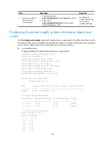
5 LST1GT48LEC1 Normal S12500-CMW520-A1221
6 NONE Absent NONE
7 NONE Absent NONE
8 NONE Absent NONE
9 NONE Absent NONE
10 NONE Absent NONE
11 NONE Absent NONE
12 LST1SF08B1 Normal S12500-CMW520-A1221
13 LST1SF08B1 Normal S12500-CMW520-A1221
14 LST1SF08B1 Normal S12500-CMW520-A1221
15 LST1SF08B1 Normal S12500-CMW520-A1221
16 LST1SF08B1 Normal S12500-CMW520-A1221
17 LST1SF08B1 Normal S12500-CMW520-A1221
18 LST1SF08B1 Normal S12500-CMW520-A1221
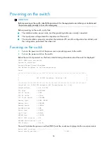
•
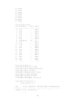
In IRF mode:
Slot No. Brd Type Brd Status Software Version
1/0 NONE Absent NONE
1/1 LST1MRPNC1 Master S12500-CMW520-A1221
1/2 NONE Absent NONE
1/3 NONE Absent NONE
1/4 NONE Absent NONE
1/5 LST1GT48LEC1 Normal S12500-CMW520-A1221
1/6 NONE Absent NONE
1/7 NONE Absent NONE
1/8 NONE Absent NONE
1/9 NONE Absent NONE
1/10 NONE Absent NONE
1/11 NONE Absent NONE
1/12 LST1SF08B1 Normal S12500-CMW520-A1221
1/13 LST1SF08B1 Normal S12500-CMW520-A1221
1/14 LST1SF08B1 Normal S12500-CMW520-A1221
1/15 LST1SF08B1 Normal S12500-CMW520-A1221
1/16 LST1SF08B1 Normal S12500-CMW520-A1221
1/17 LST1SF08B1 Normal S12500-CMW520-A1221
1/18 LST1SF08B1 Normal S12500-CMW520-A1221
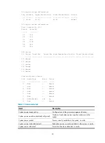
Table 16
Command output
Field Description
Slot No.
•
In standalone mode:
Slot No.
—Slot number of a card
•
In IRF mode:
Slot No.
—Slot number of a card on the specified member switch in the format of
member ID/slot number
Summary of Contents for S12500 Series
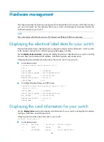
Page 40: ...30 Figure 28 Installing an upper expansion cable management bracket 1 2 3 4 5 6 7...
Page 109: ...99 Figure 74 Replacing a card for the S12504 A Card to be removed B Card to be installed...
Page 149: ...139 Figure 85 Loopback operation on an optical transceiver...
Page 164: ...154 Figure 100 Example of a device label...


