


60
3.
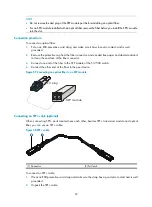
Insert one end of the plug of the SFP+ cable horizontally into the SFP+ slot on the switch and the
other end of the plug into the SFP+ slot of the peer device.
NOTE:
•
SFP+ cables are hot swappable.
•
When connecting an SFP+ cable, make sure the bend radius of the cable is no less than eight times of
the diameter of the cable.
Installing fiber management tray (optional)
NOTE:
The installation method described below is based on an N68 rack. The installation procedure is only for
your reference if you use a non-N68 rack.
A fiber management tray (FMT) is installed in a rack for winding redundant fibers between the S12500
and other devices.
•
Preparations
Confirm the following prerequisites:
{
The rack is fixed.
{
The switch is installed.
The installation involves the following materials:
{
FMT
{
M5×10 self-tapping screws (two screws for one FMT)
•
Installation procedure
To install the fiber management tray:
a.
Align the FMT and the installation holes on the column of the rack.
b.
Use a Phillips screwdriver to fix each FMT with two M5×10 self-tapping screws.
Figure 59
Installing FMTs
Summary of Contents for S12500 Series
Page 40: ...30 Figure 28 Installing an upper expansion cable management bracket 1 2 3 4 5 6 7...
Page 109: ...99 Figure 74 Replacing a card for the S12504 A Card to be removed B Card to be installed...
Page 149: ...139 Figure 85 Loopback operation on an optical transceiver...
Page 164: ...154 Figure 100 Example of a device label...


