


42
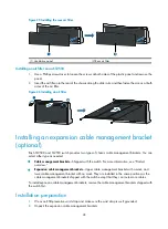
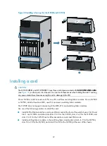
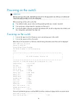
Figure 40
Installing a fan tray (for the S12508 and S12518)
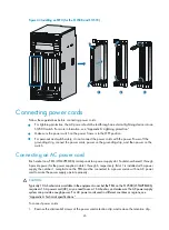
Installing a card
CAUTION:
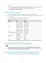
The LST1XP32REB1 and LST1XP32REC1 have three circled areas marked with
HAND OPERATION AREA
(see
) on their print circuit board. You can touch these areas when holding the card. Touching
any area outside these three areas might result in damage to the LPU.
On an S12504, install at least one MPU, one LPU, and three switching fabric modules. On an S12508
or S12518, install at least one MPU, one LPU, and seven switching fabric modules.
The S12500 does not support intermixing of the MPU, LPU, and switching fabric modules.
Use one of the following positions to install the card:
•
Install MPUs, Ethernet interface cards, and OAA cards at the front of the switch chassis. Slot 0 and
Slot 1 are for MPUs and other slots (slots 2 to 5 for the S12504, slots 2 to 9 for the S12508, and
slots 2 to 19 for the S12518) are for Ethernet interface cards and OAA cards.
•
Install switching fabric modules in the switching fabric module slots (slots 6 to 9 for the S12504,
slots 10 to 18 for the S12508, and slots 20 to 28 for the S12518) at the rear of the chassis.
Summary of Contents for S12500 Series
Page 40: ...30 Figure 28 Installing an upper expansion cable management bracket 1 2 3 4 5 6 7...
Page 109: ...99 Figure 74 Replacing a card for the S12504 A Card to be removed B Card to be installed...
Page 149: ...139 Figure 85 Loopback operation on an optical transceiver...
Page 164: ...154 Figure 100 Example of a device label...


