


9
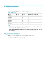
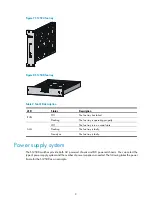
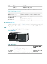
Figure 7
S12504 fan tray
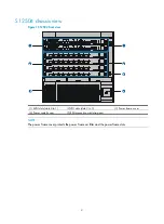
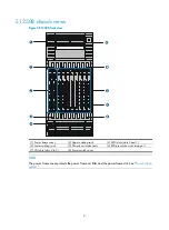
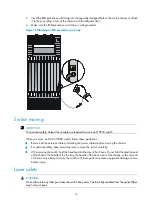
Figure 8
S12508 fan tray
Table 2
Fan LED description
LED Status Description
RUN
Off
The fan tray has failed.
Flashing
The fan tray is operating properly.
ALM
Off
The fan tray is in a normal state.
Flashing
The fan tray is faulty.
Steady on
The fan tray is faulty.
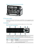
Power supply system
The S12500 switches provide both AC powered chassis and DC powered chassis. You can select the
type of power supply system and the number of power supplies as needed. The following takes the power
frame for the S12508 as an example.
Summary of Contents for S12500 Series
Page 40: ...30 Figure 28 Installing an upper expansion cable management bracket 1 2 3 4 5 6 7...
Page 109: ...99 Figure 74 Replacing a card for the S12504 A Card to be removed B Card to be installed...
Page 149: ...139 Figure 85 Loopback operation on an optical transceiver...
Page 164: ...154 Figure 100 Example of a device label...


