


22
•
For moving the switch and servicing the modules, make sure the width of the aisle in the equipment
room is at least 0.8 m (2.62 ft).
•
The equipment room is at least 3 m (9.84 ft) high.
•
Reserve at least 0.8 m (2.62 ft) of clearance between the rack and walls or other devices.
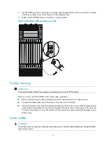
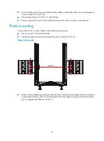
Rack-mounting
To mount the switch in a rack, adhere to the following requirements:
•
Use a four-post 19 inch standard rack.
•
The distance between the left and right rack posts is 465 mm (18.31 in).
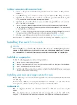
Figure 20
Rack width
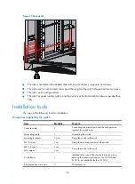
•
Make sure the available space between the front rack post and the outer edge of the front rack door
is greater than 180 mm (7.09 in) and the depth of the rack (distance between the front and back
doors) is greater than 800 mm (31.50 in).
Summary of Contents for S12500 Series
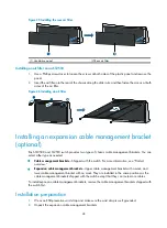
Page 40: ...30 Figure 28 Installing an upper expansion cable management bracket 1 2 3 4 5 6 7...
Page 109: ...99 Figure 74 Replacing a card for the S12504 A Card to be removed B Card to be installed...
Page 149: ...139 Figure 85 Loopback operation on an optical transceiver...
Page 164: ...154 Figure 100 Example of a device label...


