


18
Cleanness
Dust buildup on the chassis may result in electrostatic adsorption, which causes poor contact of metal
components and contact points, especially when indoor relative humidity is low. In the worst case,
electrostatic adsorption can cause communication failure.
Table 10
Dust concentration limit in the equipment room
Substance
Concentration limit (particles/m
3
)
Dust particles
≤
3 x 10
4
(no visible dust on the tabletop over three days)
NOTE:
Dust particle diameter
≥
5
μ
m
The equipment room must also meet strict limits on salts, acids, and sulfides to eliminate corrosion and
premature aging of components, as shown in
Table 11
Harmful gas limits in the equipment room
Gas Average (mg/m
3
)
Max. (mg/m
3
)
SO
2
0.3 1.0
H
2
S 0.1 0.5
NO
2
0.004
0.15
NH
3
1.0 3
Cl
2
0.1 0.3
EMI
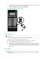
All electromagnetic interference (EMI) sources, from outside or inside of the switch and application
system, adversely affect the switch in a conduction pattern of capacitance coupling, inductance coupling,
electromagnetic wave radiation, or common impedance (including the grounding system) coupling. To
prevent EMI, take the following actions:
•
If AC power is used, use a single-phase three-wire power receptacle with protection earth (PE) to
filter interference from the power grid.
•
Keep the switch far away from radio transmitting stations, radar stations, and high-frequency
devices.
•
Use electromagnetic shielding, for example, shielded interface cables, when necessary.
•
Route interface cables only indoors to prevent signal ports from getting damaged by overvoltage or
overcurrent caused by lightning strikes.
Grounding
Using a good grounding system to protect your switch against lightning shocks, interferences, and ESD
is essential to the operating reliability of your switch.
Make sure the resistance between the chassis and the ground is less than 1 ohm.
Summary of Contents for S12500 Series
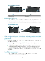
Page 40: ...30 Figure 28 Installing an upper expansion cable management bracket 1 2 3 4 5 6 7...
Page 109: ...99 Figure 74 Replacing a card for the S12504 A Card to be removed B Card to be installed...
Page 149: ...139 Figure 85 Loopback operation on an optical transceiver...
Page 164: ...154 Figure 100 Example of a device label...


