


59
NOTE:
•
Do not remove the dust plug of the SFP module port before installing an optical fiber.
•
For an SFP+ module installed with an optical fiber, remove the fiber before you install the SFP+ module
into the slot.
Connection procedure
To connect an optical fiber:
1.
Put on an ESD-preventive wrist strap, and make sure it has close skin contact, and is well
grounded.
2.
Remove the protective cap from the fiber connector, and use dust free paper and absolute alcohol
to clean the end face of the fiber connector.
3.
Connect one end of the fiber to the SFP module of the S12500 switch.
4.
Connect the other end of the fiber to the peer device.
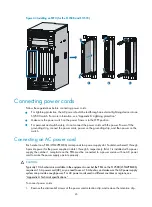
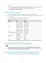
Figure 57
Connecting an optical fiber to an SFP module
Connecting an SFP+ cable (optional)
When connecting SFP+ ports located near each other, besides SFP+ transceiver module and optical
fiber, you can use an SFP+ cable.
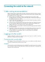
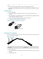
Figure 58
SFP+ cable
(1) Connector
(2) Pull latch
To connect an SFP+ cable:
1.
Wear an ESD-preventive wrist strap and make sure the strap has a good skin contact and is well
grounded.
2.
Unpack the SFP+ cable.
LC plug
SFP module
Summary of Contents for S12500 Series
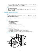
Page 40: ...30 Figure 28 Installing an upper expansion cable management bracket 1 2 3 4 5 6 7...
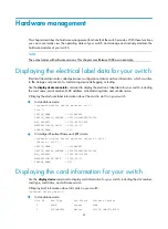
Page 109: ...99 Figure 74 Replacing a card for the S12504 A Card to be removed B Card to be installed...
Page 149: ...139 Figure 85 Loopback operation on an optical transceiver...
Page 164: ...154 Figure 100 Example of a device label...


