


75
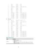
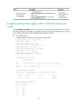
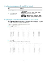
Table 18
Command output
Field Description
Slot
•
In standalone mode:
Slot
—A number in this field indicates a card.
•
In IRF mode:
Slot
—The
chassis-number/slot-number
in this field indicates a card on an IRF member
switch.
Sensor
Temperature sensor:
•
hotspot
—Hotspot sensor.
•
inflow
—Air inlet sensor.
•
outflow
—Air outlet sensor.
Temperature Current
temperature.
Lower limit
Lower temperature threshold.
WarningLimit
Warning temperature threshold.
AlarmLimit
Alarming temperature threshold.
ShutdownLimit
Shut-down temperature threshold (currently not supported).
Isolating a card and locating card faults
When the switch detects a card failure or upgrades a logic of the CPU daughter card on a card, you can
isolate the faulty card or the CPU daughter card to prevent it from forwarding data packets. This
operation allows for convenient on-site fault location or upgrading while causing no interference on the
operation of the system and services of other cards.
Configuration restrictions and guidelines
•
The active MPU cannot be isolated.
•
If only one switching fabric module is working on the switch, it cannot be isolated.
•
Before upgrading a logic of the LPU, keep the LPU offline.
•
To minimize the interference on the system operation, force a switching fabric module that is
operating normally offline before you unplug it.
•
You can use the
display device
command to view whether a card is isolated, or, whether the card
is in the offline state.
•
No other commands but the
test diag-offline
command can be executed for an isolated card.
Otherwise, the configuration cannot take effect. After isolating a card, you can use the
test
diag-offline
command to collect the fault detection information of the card. The path where the fault
detection information is saved is also displayed following the fault detection information on the
terminal. For example, you can see flash:/diag_slot3_20080522_103458.txt.
•
Deliver the fault detection information to the H3C technical engineers or engineers of the sales
agent.
Configuration procedure
To isolate a card and locate card faults:
Summary of Contents for S12500 Series
Page 40: ...30 Figure 28 Installing an upper expansion cable management bracket 1 2 3 4 5 6 7...
Page 109: ...99 Figure 74 Replacing a card for the S12504 A Card to be removed B Card to be installed...
Page 149: ...139 Figure 85 Loopback operation on an optical transceiver...
Page 164: ...154 Figure 100 Example of a device label...


