


STR 632
Allgemeiner T
eil / General Section
GRUNDIG
Service
1 - 19
Recording satellite programmes
(Timer)
If your receiver is connected to a video recorder,
you can record satellite programmes.
❒
Starting recording manually
Select the desired channel position on the receiver.
Select the channel position for the satellite receiver
on the video recorder and start recording.
❒
Programming recordings
You can programme your receiver so that it
receives up to eight events within a period of 28
days and passes these on to your video recorder
while you are not at home.
Of course the timer of your video recorder must be
programmed correspondingly.
Press the
.
button on the remote control unit
twice.
– The ”MAIN MENU” appears.
Press the
1
button.
– The TIMER menu appears with the digit next to
”TIMER” flashing.
Use the
] |
buttons to select the data you wish
to change.
Use the
c x
buttons to change the data.
The selected value is flashing.
The time and the programme position number can
also be entered with the numeric buttons.
w
!
If your video recorder is connected via an aerial
lead with the receiver, you must perform the
settings described on page 7.
w
!
It is not possible to simultaneously record a
satellite programme and view another satellite pro-
gramme.
6
6
2
1
2
1
k
Using the Receiver
If you wish to programme a video recorder via VPS,
the satellite receiver should be switched on a little
before and switched off after the broadcast to be
recorded (to be programmed via the Timer). This
makes sure that the broadcast will completely be
recorded even if there should be shifts of the start
and end times. If you wish to make absolutely sure
that the broadcast is completely recorded, the SAT
receiver must permanently be switched on and set
to the desired programme position.
Select a Timer.
Select the channel index and the programme posi-
tion you wish to use for the programmed recording.
Enter the week (1…4) and the day for the recording
(1 and MON = monday first week, 2 and TUE = tues-
day second week …), as well as
the start time in hours and minutes,
the stop time in hours and minutes.
Check to see whether the time and date are correct-
ly set (summer/winter time, mains failure).
For daily repeated programmes, use the ”DAILY”
option instead of entering the day of the week.
When the timer has elapsed, it will automatically be
switched to standby for the next day. This function
is not limited to four weeks. However, if the
programme is not broadcast during the weekend,
the timer must be switched off for these days.
For weekly repeated programmes, use the
”WEEKLY” option instead of entering the week.
When the timer has elapsed, it will automatically be
switched to standby for the same day in the next
week.
If you change a timer setting, the timer status is
automatically switched to ”ON”.
Save the settings with the
O
button.
If the programme position should be locked, you
are prompted to enter the access code (PIN).
w
!
If you enter the wrong code, all timer settings for
locked programme positions are inhibited and must
individually be enabled by entering the correct
code.
Press the
.
button to terminate timer program-
ming.
8
7
6
6
6
6
5
4
3
6
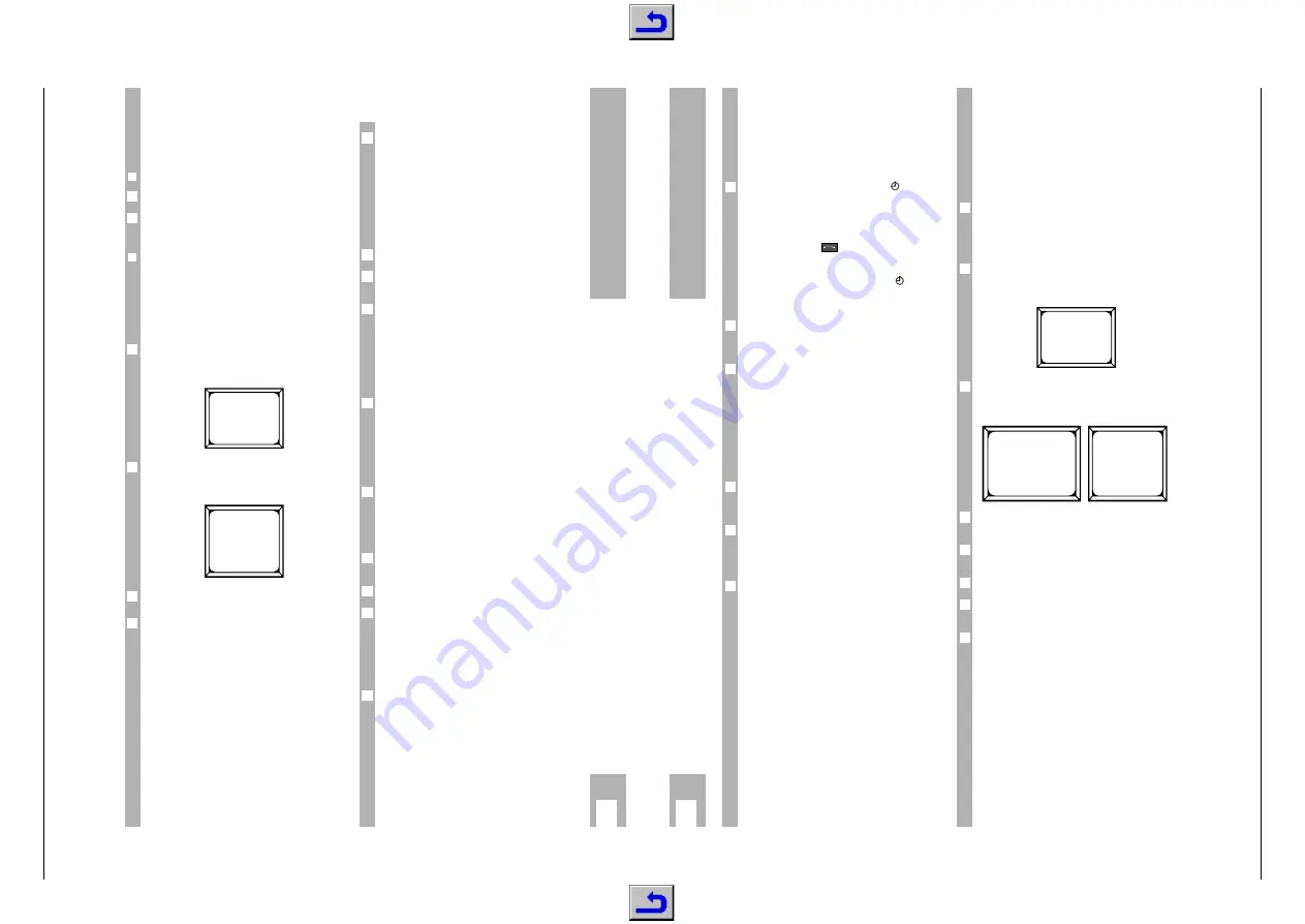
MAIN MENU
1 TIMER
2 INSTALL
3 CHANNEL SETUP
4 LOCK CONTROL
PRESS 1-4 OR I
TIMER
1
STATUS OFF
MODE
NORMAL
CHAN.
001
ARD
WEEK
1
DAY
SUN
START
20:15
STOP
22:00
TIME
18:00 SUN
PRESS OK OR I
w
!
When the programmed recording time (”event”)
arrives, the receiver must be in standby mode. The
receiver then is automatically switched on.
w
!
If you use the receiver otherwise when the pro-
grammed event arrives, it cannot start the program-
med recording.
If a Timer is programmed, the symbol
is visible
in the receiver's display.
If the first event is active, "
EVENT 1 ON
" appears
in the display.
If the video recorder is connected via the "AUX 2"
euroconnector, the
symbol is lit in the recei-
ver's display as long as the video recorder is in
operation.
If no further event is programmed, the
symbol
disappears after the recording and the receiver
switches to standby.
If you wish to cancel an activated timer, switch the
receiver briefly to standby (
b
botton or
¢
8
botton
on the receiver).
If the video recorder is connected via the ”AUX 2”
euroconnector to the receiver, ”
VCR
” is visible in
the receiver’s display. If the receiver is not automa-
tically switched in the VCR mode, you must do this
manually as described in the following paragraph.
Switching between SAT, TV and
VCR mode
Use the
,
A / B
button to switch between SAT, TV
and VCR mode. In most cases, switching takes
place automatically.
In the menu mode, the
,
A / B
button has a different
function (background on/off). For switching be-
tween SAT, TV and VCR mode, you must therefore
exit the menu mode.
The modes have the following meaning.
The SAT mode is used for Satellite reception. A high
signal is applied at PIN 8 of the TV socket and a
video recorder connected to this socket loops the
signal through to the TV set.
In the VCR mode, the ”
VCR
” indication appears in
the receiver’s display. The signal applied at the
AUX 2 socket is looped through to the TV socket
and to the modulator (TV/VCR socket). This mode
is used for video playback. When starting video
playback, the receiver is in most cases automatical-
ly switched in VCR mode (an impulse is applied at
Pin 8 of the AUX 2 socket). When selecting another
programme position on the receiver, the VCR mode
is automatically terminated.
6
6
1
6
6
6
k
Using the Receiver
In TV mode, ”
TV
” appears in the receiver’s display.
The switching signal is removed from Pin 8 and the
receiver switches to normal reception of terrestrial
TV programmes.
Contrast preselection (video
amplitude)
To get an optimum picture contrast, the receiver
must be adjusted to the satellite signal.
You can preselect three different contrast ranges
(from 1 to 64).
Press the
.
button on the remote control unit
twice.
– The ”MAIN MENU” appears.
Press the
2
button and then the
3
button.
– The ”INSTALL” and ”DECODER/AV” menus
appear one after the other.
Use the
] |
buttons to select the respective
menu line.
Use the
c x
buttons to adjust the optimum pic-
ture contrast.
Save the setting with the
O
button .
Press the
.
button twice to terminate the contrast
adjustment.
In the ”CHANNEL SETUP/TUNING” menu, you can
select the correct setting for your satellite pro-
gramme (see paragraph "Establishing a new
programme position”).
6
6
5
4
3
2
1
6
MAIN MENU
1 TIMER
2 INSTALL
3 CHANNEL SETUP
4 LOCK CONTROL
PRESS 1-4 OR I
INSTALL
1
LNC SETUP
2
CUSTOM AUDIO
3
DECODER/AV
4
LANGUAGE
PRESS 1-4 OR I
DECODER/AV
CONT. 1
20
CONT. 2
40
CONT. 3
60
AUX1
DEC
MODE AUTO
VIDEO NORMAL
AUX2
VCR
PRESS OK OR I


