5-11
Chapter 5 FUNCTION SETTINGS AND OPERATIONS
5.10 Assigning Perforation Cutting
This function allows you to assign the perforation cutting operation to COND Nos. 1 to 8.
(1) Press the
[PAUSE] key
to select PAUSE mode.
(2) Press the
[NEXT] key
repeatedly until the following menu is displayed.
FORCE
OFFSET
SPEED
QUALITY
I/F FUNCTION
TOOL COND AREA OPT
(3) Press the
[F3] key
(TOOL COND) to display the menu shown below.
FORCE
OFFSET
SPEED
QUALITY
THICK CUT LINE
TOOL No. ADJ.T POS
(4) Press the
[F3] key
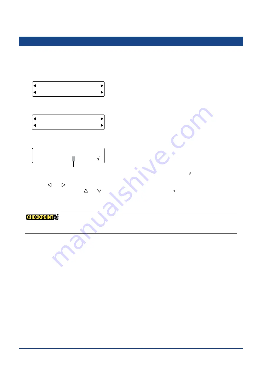
(CUT LINE) to display the perforation cutting operation assignment setting screen.
FORCE
OFFSET
SPEED
QUALITY
COND. No. 12345678
CUT LINE
Blinking cursor
The upper row of the display represents the cutting condition COND Nos. A check mark [ ] is displayed for any of
the COND. Nos. to which the perforation cutting operation has been assigned.
Use the
[
]
or
[
]
key
to move the blinking cursor to the COND. No. that you want to assign the perforation
cutting operation to, and the
[
]
or
[
]
key
to display or hide the check mark [ ].
Press the
[ENTER] key
to con
fi
rm your selections.
(5) Press the
[PAUSE] key
to cancel PAUSE mode.
•
These settings are retained in the plotter's internal memory even while the plotter is turned off.
•
Please see Section 3.8, "Setting the Cutting Conditions" for details on perforation settings.
Summary of Contents for CUTTING PRO FC2250 Series
Page 1: ...USER S MANUAL MANUAL NO FC2250 UM 151 FC2250 SERIES CUTTING PRO www delinit by...
Page 104: ...5 29 Chapter 5 FUNCTION SETTINGS AND OPERATIONS Cutting Plotting Conditions List...
Page 120: ...CHAPTER 8 SPECIFICATIONS PRODUCT SUMMARY 8 1 Main Specifications 8 2 External Dimensions...
Page 129: ...www delinit by...


