3-13
Chapter 3 PREPARATIONS FOR CUTTING/PLOTTING
(5) Use the
[
]
or
[
] key
to move the position of the blinking cursor, and the
[
]
or
[
] key
to select the value.
Setting range: 0 to 9.99 mm
Mode 2 (Crease two lines)
Mode 3 (Crease three lines)
Actual data
(creasing is not performed
at the actual data position)
Spacing
Actual data
Spacing
Setting the Number of Creasing Operations
(6) Press the
[F3] key
to move the blinking cursor to the position shown in the following screen.
FORCE
OFFSET
SPEED
QUALITY
MODE2 COUNT1
SPC 1.00mm ST 0.00mm
(7) This setting determines how many times creasing should be repeated for each line segment. Use the
[
]
or
[
]
key
to select the value.
Setting range: 1 to 9 (times)
Setting the Start and End Positions
(8) Press the
[F4] key
to move the blinking cursor to the position shown in the following screen.
FORCE
OFFSET
SPEED
QUALITY
MODE2 COUNT1
SPC 1.00mm ST 0.00mm
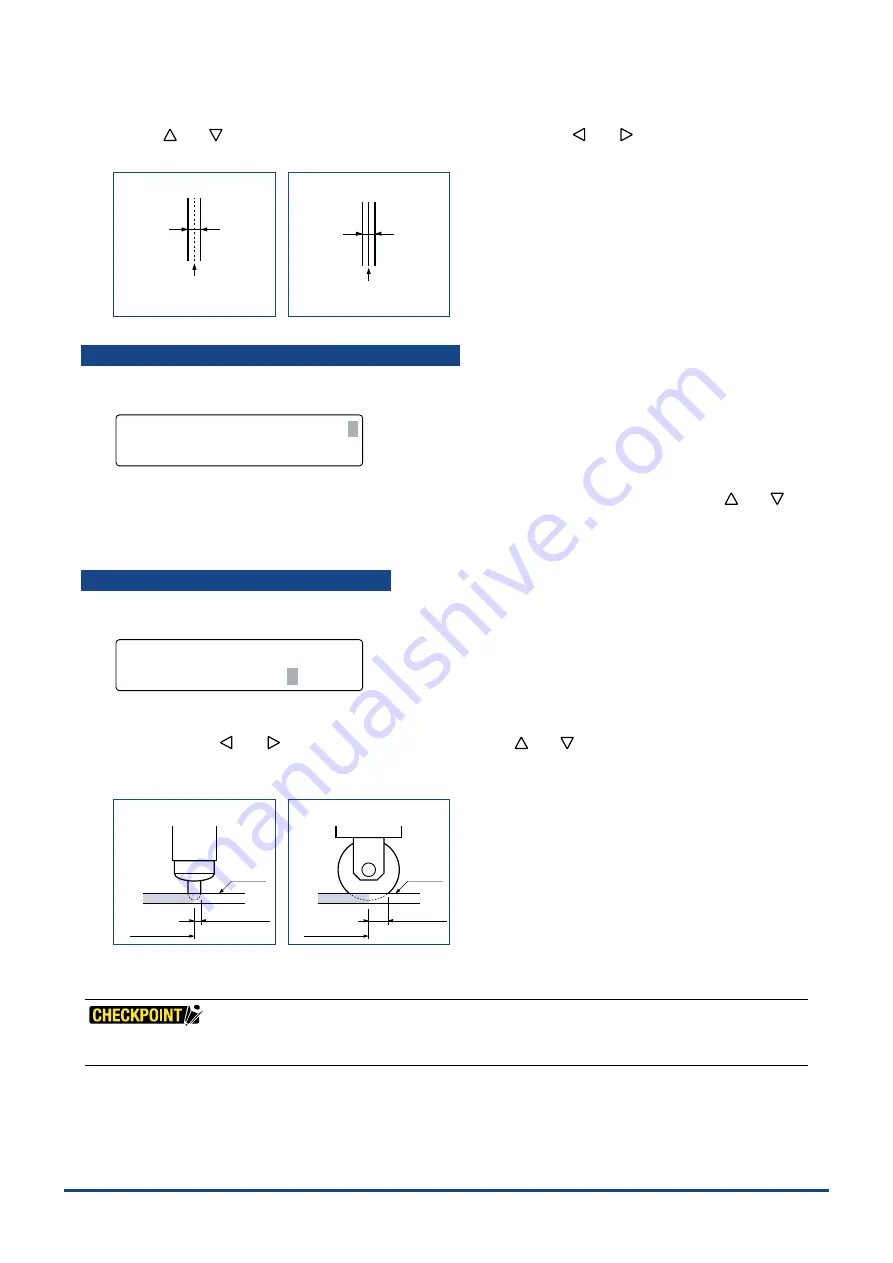
(9) This setting determines by what margin each end of the creasing line falls short of the corresponding end of the actual
data line. Use the
[
]
or
[
]
key
to move the blinking cursor, the
[
]
or
[
]
key
to change the numeric value and
the
[ENTER] key
to con
fi
rm your selections.
Setting range: 0 to 9.99 (mm)
CP-002/003
CP-001
Actual data
Specified value
Medium
Actual data
Specified value
Medium
(10) When all the displayed values are correct, press the
[ENTER] key
. To cancel your settings, press the
[NEXT] key
.
For short-line data such as circle command data, setting a large value for the ST (Start) parameter may result in creasing
not being performed.
Summary of Contents for CUTTING PRO FC2250 Series
Page 1: ...USER S MANUAL MANUAL NO FC2250 UM 151 FC2250 SERIES CUTTING PRO www delinit by...
Page 104: ...5 29 Chapter 5 FUNCTION SETTINGS AND OPERATIONS Cutting Plotting Conditions List...
Page 120: ...CHAPTER 8 SPECIFICATIONS PRODUCT SUMMARY 8 1 Main Specifications 8 2 External Dimensions...
Page 129: ...www delinit by...


