Repair Manual MSG 90.6PG Commercial Vehicles, Omnibuses – November 2017
Material no. 1153450_c
3.17 Bowden pull wire for seat angle adjustment with locking mechanism –
removal and installation
Page 6 of 9
REMOVAL INSTALLATION
TABLE OF CONTENTS
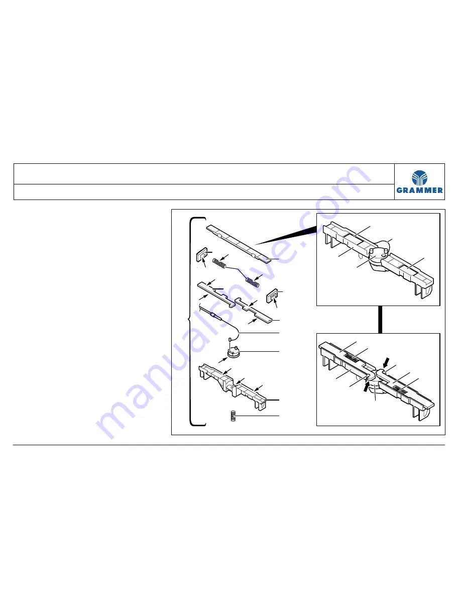
6 Apply acid-free multi-purpose lubricant
(F) to the compression springs (8).
7 Hang in compression springs (8) into
the latches (6) and press them into the
pockets (12) of the housing (3).
8 Checking the installation position:
The compression springs (8) must
press the latches (6) to the outside
while the nose (arrow) of the latch (6)
must embrace the respective pin (13)
of the catch element (4).
9 Press the cover (9) onto the latches
(6) and compression springs (8) and
lock it together with the housing (3).
5
3
4
12
12
13
3
13
4
8
6
6
8
F
7
7
F
F
F
F
F
F
F
F
F
F
F
9
3
2
6
6
8
1
5
4
2207


