background image

GBESS 2.4_4.8KWH system user manual                                                     


35 


WAIT

KW

KW

KW

KW

KW

KWh

INVERTER EXPERT

EOUT 

MDE


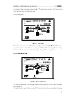
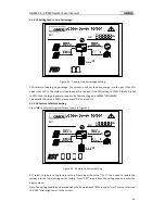
Figure 44    Time-of-use Mode Setting 

WAIT

KW

KW

KW

KW

KW

KWh

INVERTER EXPERT

EOUT 


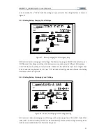
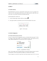
Figure 45    Charging Time Range Setting Under Time-of-use Operation Mode 

WAIT

KW

KW

KW

KW

KW

KWh

INVERTER EXPERT

EOUT 


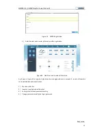
Figure 46    Discharging Time Range Setting under Time-of-use Operation Mode 


Summary of Contents for GBESS 2.4 4.8KWH

Page 1: ... GBESS 2 4_4 8KWH Next generation battery inverter and system solution User Manual Version 1 1 ...

Page 2: ... 5 2 2 System Connection 6 3 System installation 7 3 1 Unpacking the Device 7 3 1 1 Before Unpacking 7 3 1 2 Mounting 8 3 1 3 Packing List 10 3 2 Mounting 13 3 2 1 SolDate 3100 3700TL and BM024 Installation 13 3 2 2 Mounting Battery Cabinet 14 3 2 3 Mounting Energy Meter 18 3 3 System Connection 20 3 3 1 How to Make Power Connecting Line 21 3 3 2 RS485 Communication Line 22 3 3 3 System Connection...

Page 3: ... Wi Fi Function 40 4 2 2 Wi Fi Configuration 40 5 System Operation 44 5 1 System Settings 44 5 2 System Starting 44 5 3 System Operating Instructions 45 5 3 1 On grid Operation 45 5 3 2 Off grid Operation 45 5 4 System Maintenance 45 6 Troubleshooting 46 6 1 Safety during Troubleshooting 46 6 2 Faults 46 6 3 Fault Messages and Actions List 46 6 4 Fault Acknowledgement 49 6 5 Technical Service 49 ...

Page 4: ...9 Fax 86 21 61730300 www global mde com All information in this documentation has been compiled and checked with most care Despite of this faults or deviations cannot be completely excluded We assume no liability and are hereby acknowledged The relevant up to date version can be obtained from www global mde com The details of this documentation are the property of GMDE Using and publicizing this d...

Page 5: ...he manual please note that you can click the content to find information you want quickly All the characters with underline are clickable A phrase named Back to Top at the bottom of each chapter can help you go back to the first page quickly Before using this device please ensure that you have read this manual including installation and safety operation carefully If you have any difficulties durin...

Page 6: ...ith the general safety rules for working with electrical equipment This manual is intended for qualified electricians 1 2 Safety Rules General introduction These safety related guidelines use the following warning notices to describe the various levels of danger Death or severe personal injury will occur DANGER Death or severe personal injury may occur WARNING Personal injury or material damage ma...

Page 7: ...shearing cutting or striking CAUTION Cancellation of the operating license If the GMDE inverter is operated with a wrong country code the electric supply company may cancel the operating license CAUTION Hot surface Surfaces of the housing can be hot Risk of injury Risk of burns The housing top and the heat sinks may have a surface temperature of 70 C HOT SURFACE 1 3 Warning Notices Affixed to the ...

Page 8: ...attery packs wait at least 15 minutes before proceeding Operating the product Do not commission the device until the whole system complies with the application specific national rules and safety regulations The ambient conditions given in the product documentation must be observed The device manufacturer or installer is responsible for compliance with the limit values as prescribed in the national...

Page 9: ... any personal injury any damage or injury arising from or as a result of misuse or abuse or the incorrect installation integration or operation of the product We disclaim any liability for direct or indirect damages due to 1 Improper installation or commissioning 2 Modifications alterations or repair attempts 3 Inappropriate use or operation 4 Insufficient ventilation of the device 5 Non complianc...

Page 10: ... four modules Soldate 3100 3700 TL BM024 battery manager lithium battery packs and energy meter A B C D Figure 2 Main System Components 1 SolDate3100 3700TL inverter The inverter converts the DC power from BM024 into AC power The electricity from battery is used by the household loads or fed into the grid 2 BM024 battery manager In connection with the SolDate3100 3700TL via DC bus line BM024 batte...

Page 11: ...amily from power outages PV Inverter DC AC DC AC Geatom103KHF DC AC DC AC PV GRID LOAD K battery BAT S E T Single Energy Meter L N L N 5 6 7 8 K inv Grid K load Meter for Grid K el Emergency Load Load S E T Single Energy Meter L N L N 5 6 7 8 K pv Meter for PV Figure 3 System Wiring Diagram meter for grid without CT Attention The nominal current of meter is only 20A If the power of load and emerge...

Page 12: ...efore Unpacking All products are thoroughly tested and inspected before they re packed and transported Although they re shipped in reliable package damage during transportation could still occur It is important to inspect the shipping package prior to the installation carefully If any external damage on the package makes you suspect the device could be damaged or if you find that the device is dam...

Page 13: ...t power if the ambient air temperature exceeds 45 C The cooler the air temperature the longer the life expectancy of any electronics device 4 The installation space for GEatom103KHF and battery cabinet please refer to the device dimension figure and installation space figure Figure 6 Figure 8 5 The system should be installed in a location where is inaccessible to children 6 The device is designed ...

Page 14: ...binet Dimension Module SolDate3100 3700TL BM024 Battery Cabinet Dimension L W D mm 500 x 380 x 150 500 x 280 x150 570 x 600 x245 Weight kg 25 10 15 cabinet 25 2 battery Table 1 Main Modules Specification Battery Pack 245 0 600 0 482 0 500 0 280 0 380 0 500 0 300 300 200 200 170 0 To Meter DC BREAKER To Cabinet To Inverter Figure 8 Installation Space ...

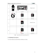
Page 15: ...lDate3100 3700TL mounting bracket 1 A3 Expansion Tube 4 A4 Tapping Screws 4 A5 Aviation Plug Female for AC grid connection x 1 1 A6 Aviation Plug Male Connector for emergency load connection x1 1 A7 GBESS 2 4_4 8KWH system user manual 1 Table 2 SolDate 3100 3700TL Packing List 3 1 3 2 BM024 Packing List B2 B3 B4 B5 B6 Figure 10 BM024 Packing List Item Description pcs B1 BM024 battery manager 1 B2 ...

Page 16: ...ist 3 1 3 3 Unpacking Battery Cabinet Battery Pack C2 C1 C3 C4 Figure 11 Battery Cabinet Packing List Item Description pcs C1 Battery cabinet 1 C2 Battery cabinet mounting bracket 1 C3 Expansion Tube 4 C4 Tapping Screws 4 Table 4 Battery Cabinet Packing List 3 1 3 4 Unpacking Battery Packs RS485 Link Port0 ON OFF COM1 COM3 NO1 NO3 SW PO WER ADD RUN Console SOC ALM CAN Link Port1 IN GND NO2 COM2 Fi...

Page 17: ... list D1 Energy meter 1 phase 2 D2 Communication line between meter and battery cabinet 1 D3 DC connection line between BM024 and battery cabinet 1 D4 Communication line between SolDate3700TL and battery cabinet 1 D5 Communication line between two battery modules 1 D6 Positive power line between two battery modules 1 D7 Negative power line between two battery modules 1 D8 Communication line betwee...

Page 18: ...Energy Meter If the current flow through the meter large than 20A a CT is recommended to add L N L N 5 6 7 8 SET Single Energy Meter 1 2 3 4 S2 S1 P1 30I 1 4 L L 5 6 7 8 A ADL 100 E C Single Phase Energy Meter 12800imp kWh 50Hz GB T 17215 321 2008 DATE 06 06 16 220V Address 002 B 1 L N Load RS485 kWh 99999999999999 1 5 6 A 200 5 Meter for Grid with CT Optional D3 CT Optional Figure 15 Energy Meter...

Page 19: ...acket B2 on the wall and mark it 2 Use Φ10 drill template to drill holes on marked position 3 Fix the expansion bolt B3 in the hole 4 Fix wall bracket B2 on the wall 5 Fix screw B4 through wall bracket B2 to expansion bolt B3 adjust the bracket position and screw up 6 Align with wall bracket B2 move BM024 B1 in horizon direction at proper position 7 Make the hook on wall bracket B2 insert into the...

Page 20: ...e top cover to finish the battery packs installation into the cabinet Figure 18 Install Battery Modules into Battery Cabinet 3 2 2 2 Mounting battery cabinet C1 1 Choose a proper position for the bracket C2 on the wall and mark it 2 Use Φ10 drill template to drill holes on marked position 3 Fix the expansion bolt C3 in the hole 4 Fix wall bracket C2 on the wall 5 Fix screw C4 through wall bracket ...

Page 21: ...y cabinets to RS485 port of first battery module and take this first battery module as master battery 2 Connect the port Link Port 1 of first battery to the port Link Port 0 of second battery with the communication cable 3 The port Link Port 1 of second battery you can leave it free 4 Connect one of positive pole of two battery modules and one of negative pole of two battery modules with the power...

Page 22: ...Link Port 0 of fourth battery module with a communication cable 11 Connect the port To Cabinet on battery cabinet 1 to port To Cabinet on battery cabinet 2 with a communication cable SOC ALM SW AD D CAN RS485 Link Port0 Link Port1 POWE R ON OFF IN COM1 COM3 NO1 NO2 NO3 GND SW POWE R ON OFF AD D RUN RUN Console Console SOC ALM RS485 CAN Link Port1 Link Port0 IN GND NO1 COM1 NO2 COM2 NO3 Cabinet 1 D...

Page 23: ...hold Gateway meter Figure 22 Meter Installation Position Please pay attention to the direction of Energy meter L N port on the meter is to connect with the public grid L N port is to connect with the GRID port of the Geatom103KHF system Distribution box Load SET Single Energy Meter L N L N 5 6 7 8 Load Grid Distribution box SET Single Energy Meter L N L N 5 6 7 8 Distribution box Load Grid SET Sin...

Page 24: ...Figure 24 L L N N 5 6 7 8 A ADL 100 E C Single Phase Energy Meter 800imp kWh 50 60Hz GB T 17215 321 2008 DATE 06 06 16 220V B 1 99999999999999 L N Load RS485 kWh 20 80 A Address 001 Figure 24 Meter Address Warning Please ensure the grid is disconnected before installation Caution The maximum current stand by energy meter is 80A Caution A standard AC breaker should be installed after the GRID port ...

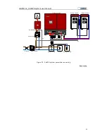
Page 25: ...RS485 Ethernet BUS TO PV CAN BAT BAT CHG DISCHG Distribution box Load Meter for Grid Emergency load PV PANEL GEatom 103KHF Battery Cabinet B5 B6 D3 F3 F4 SET Single Energy Meter L N L N 5 6 7 8 PV INVERTER DC Meter for PV SET Single Energy Meter L N L N 5 6 7 8 D2 D8 D4 L N K GRID Figure 25 Connecting Demonstration for Standard Lithium Battery Storage System ...

Page 26: ...uld be lower than 4 2kW 2 The emergency load connected should be no more than 2kW 3 A 32A 400V AC Breaker and 300mA leakage protector should be installed between the system and the grid 4 A 16A 400V AC Breaker and 300mA leakage protector should be installed between the system and the emergency load 3 3 1 How to Make Power Connecting Line Figure 27 Figure 28 are the connecting demonstration for PV ...

Page 27: ...nication Line GMDE inverter uses RJ45 jacks as the RS485 communication port The RJ45 plug pin allocation is illustrated by figure 25 Figure 29 RJ45 plug pins allocation Pin No Illustration 1 2 3 Data 4 GND 5 GND 6 Data 7 5V 8 5V Table 8 RJ45 plug pins allocation 3 3 3 System Connection Please refer to table below and connect the power lines communication lines with correspond ports on the device r...

Page 28: ...AT BAT CHG DISCHG B6 A1 TO BAT B1 TO PV 3 PV1 PV2 BUS GRID LOAD DC Switch ON OFF WIFI TO BAT CAN RS485 Ethernet To Meter DC BREAKER To Inerter To Cabinet D4 A1 RS485 C TO Inverter 4 BUS TO PV CAN BAT BAT CHG DISCHG D3 B1 BAT C BAT Connector 5 To Meter DC BREAKER To Inerter To Cabinet SET Single Energy Meter L N L N 5 6 7 8 GRID D2 C TO Meter D1 5 6 6 PV1 PV2 BUS GRID LOAD DC Switch ON OFF WIFI TO ...

Page 29: ...T Single Energy Meter L N L N 5 6 7 8 GRID B10 D2 5 6 D1 5 6 9 SET Single Energy Meter L N L N 5 6 7 8 PV Inverter AC port D2 L N 10 SET Single Energy Meter L N L N 5 6 7 8 SET Single Energy Meter L N L N 5 6 7 8 GRID D2 L N D1 L N Table 9 Connection line and corresponding ports list 3 3 4 9 6kWhSystem Connection The connection difference between 9 6kWh and 4 8kWh system as below ...

Page 30: ...witch ON OFF WIFI TO BAT CAN RS485 Ethernet BUS TO PV CAN BAT BAT CHG DISCHG Distribution box Load Meter for Grid Emergency load PV PANEL GEatom 103KHF Battery Cabinet B5 B6 D3 F3 F4 SET Single Energy Meter L N L N 5 6 7 8 PV INVERTER DC Meter for PV SET Single Energy Meter L N L N 5 6 7 8 D2 D8 D4 L N K GRID Figure 30 9 6kWh system power line connecting Back to top ...

Page 31: ... back to the upper item or close Up Move back to the upper item or previous page Down Move forward to next item or next page OK Enter Escape Enter into or exit from the current page Table9 LCD Function Introduction 4 1 2 LCD Indication Lights Item Definition Description PV operation light Light on when hybrid inverter system is running smoothly Battery operation light Light on if the communication...

Page 32: ... the display menu To enter the setting menu long pressing the OK button for 3 seconds Choose parameters to be set by pressing buttons Parameter list and definition on display menu Item list Display content PV1 Voltage Current PV2 Voltage Current No Item Definition 1 Time Current date and time 2 Systemstatus Operating status of the inverter Wait Start Normal Warning Fault Off grid 3 Energy EIN EOUT...

Page 33: ...ioning Item Description PW Password 1111 or 6666 TIM Time TYP Battery type 00 Lithium ion battery default 01 Lead battery BVH Battery charging stop voltage default 54V BVL Battery discharging stop voltage lithium default 46V lead acid default 47V Id Max discharging current default 50A Ic Max charging current default 50A CER Certification 00 G83 default 01 VDE 0126 4105 02 AS4777 CNY PV connection ...

Page 34: ...sword input interface as Figure 34 will be displayed WAIT KW KW KW KW KW KWh INVERTER EXPERT EOUT PV1 Figure 33 Display Menu 4 1 5 1 Password WAIT KW KW KW KW KW KWh INVERTER EXPERT EOUT PW Figure 34 Setting Interface The default password for setting is 1111 or 6666 users can key in the password through pressing and OK buttons Press OK button to enter into time setting as Figure 35 showed SOC Disc...

Page 35: ...s and OK buttons to adjust the numbers on the interface successively press OK to finish the setting After time setting the system will automatic enter into the battery type settings interface as in Figure 36 4 1 5 3 Setting Battery Type WAIT KW KW KW KW KW KWh INVERTER EXPERT EOUT TYP Figure 36 Battery type setting TYP refers to battery type 00 is referring to lithium battery please set TYP as 01 ...

Page 36: ...ue for different battery types Press OK to modify setting on this parameter Make sure the BVH value input here is higher than the BVL value setting Section 4 1 5 5 Press OK to finish this setting and you will enter the setting interface as shown in Figure 38 4 1 5 5 Setting Battery Discharging Cut off Voltage WAIT KW KW KW KW KW KWh INVERTER EXPERT EOUT BVL V Figure 38 Battery Discharging Cut off ...

Page 37: ...The default value is 50A Please set this current value according to the battery recommended value of different battery types Press OK to finish this setting and you will enter the setting interface as shown in Figure 40 4 1 5 7 Setting Battery Maximum Charging Current WAIT KW KW KW KW KW KWh INVERTER EXPERT EOUT Ic A Figure 40 Battery Maximum Charging Current Setting Ic refers to the maximum charg...

Page 38: ...ulations Press OK to finish this setting and you will enter the setting interface as shown in Figure 42 4 1 5 9 Setting PV String Connection Way WAIT KW KW KW KW KW KWh INVERTER EXPERT EOUT CNY Figure 42 PV String Connection Way Setting CNY refers to the connection way of PV strings The CNY should be set to 01 when SolDate3100 3700TL only have PV1 port connected with PV string the CNY should be se...

Page 39: ... press OK to modify it If modify MDE value into 01 as shown in Figure 44 press OK the system will enter the charging time range setting interface as shown in Figure 45 For example if you want the system start to charge the battery at 22pm and stop charging at 5am next morning then please set the digits on Figure 45 as 22 00 05 00 respectively The charging current is the same as the Ic that has bee...

Page 40: ... EOUT MDE Figure 44 Time of use Mode Setting WAIT KW KW KW KW KW KWh INVERTER EXPERT EOUT Figure 45 Charging Time Range Setting Under Time of use Operation Mode WAIT KW KW KW KW KW KWh INVERTER EXPERT EOUT Figure 46 Discharging Time Range Setting under Time of use Operation Mode ...
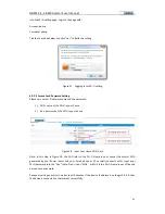
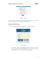
Page 41: ... EXPERT EOUT ME2 Figure 48 PV Energy Meter Address Setting ME1 and ME2 refer to energy meter address Please check the address column on energy meter label as shown in Figure 24 you will find the meter address is 001 Press OK and change the meter address to 001 accordingly Note Each meter has a unique address ensure this value is input correctly 4 1 5 12 Setting Current Transformer Ratio Press OK t...

Page 42: ...urrent transformer for indirect metering case Please check the current transfer ration listed on the current transformer label and press OK to modify it Note Different current transformer has different current ratios please input the right ratio The default value is 01 it s not necessary to modify this value if no current tranformer is connected in 4 1 5 13 Setting Lithium ion BMS Code Press OK to...

Page 43: ... 00 which is corresponding with Pylon battery Our current standard lithium battery is from Pylon so this value doesn t need to be changed Please press to enter the interface as figure 46 showed 4 1 5 14 Setting Battery State of Charge SoC WAIT KW KW KW KW KW KWh INVERTER EXPERT EOUT SOC Figure 52 SoC Setting SOC refers to the left battery capacity ratio For example if set SOC as 15 the system will...

Page 44: ... fed into the grid is 3600W 10 360W The default FED value is 100 please press OK to modify it 4 1 5 16 Restore to Factory Setting Press to enter setting interface as shown in Figure 54 WAIT KW KW KW KW KW KWh INVERTER EXPERT EOUT RST Figure 54 Restore to Factory Setting RST refers to restore to the factory setting Please input the value 1111 if you need to restore the system into the initial setti...

Page 45: ... integrated in the inverter Figure 55 Wi Fi Antenna 4 2 2 Wi Fi Configuration 4 2 2 1Get Connected with the Inverter Wi Fi End user can connect to the Wi Fi generated by inverter via smart ends like smart phone PC or iPad etc Choose the Wi Fi portal created by the corresponding inverter whose network name is GMDE_XXXXXXXX XXXXXXXX part is the Monitor SN as shown in figure below Figure 56 GEatom103...

Page 46: ...ouse 2 Key password of the Wi Fi in your house Figure 58 Input Your Home Wi Fi Data Note in this step in Figure 58 the SSID refer to the Wi Fi Name in your house the normal Wi Fi generated by your Power router and your Smart phone or PC normally connects with Input your Wi Fi password into the Key table Don t input MDE as MDE is the Wi Fi Name in our office and be input as an example Save your set...

Page 47: ...ng steps 4 2 2 2 User Account Registration Registration procedures are as following 1 Visit your website portal http portal global mde com and sign up a account Figure 60 Sign Up 2 Key in Username password e mail address and monitor SN as Figure 61 Please notice the Monitor SN is the Suffix of the GMDE_XXXXXXXX For example if the Wi Fi of one device is GMDE_3E227BB2 then the Monitor SN you should ...

Page 48: ...gure 63 Add Plant and Inverter Information As shown in Figure 63 a couple of plants can be managed under one account A couple of inverters can be added into under each plant 1 My sites plant list 2 Inverter inverters under the plant 3 Setting plant related parameter setting 4 Change password modify the log in password Back to top ...

Page 49: ...r the LCD lights on users can set parameters including password time battery type county code and operation mode etc For details please refer to section 4 1 5 LCD Setting Turn off the DC switch optional wait until the LCD screen is black out 5 2 System Starting 1 Turn on the DC breaker on the battery cabinet To Meter DC BREAKER To Inverter To Cabinet To M eter DCBREA KER To In verter To C a binet ...

Page 50: ... set charging time discharges the battery packs at peak time pre set discharging time 5 3 2 Off grid Operation The GEatom 103KHF battery inverter has integrated backup function Note maximum charging current maximum discharging current discharging stop voltage and charging stop voltage should be set before commissioning to maintain battery s lifetime These parameters are set in LCD screen 5 4 Syste...

Page 51: ... a temporary failure A permanent failure is defined by a fault having been present for more than 15 minutes and cannot be acknowledged by inverter s auto restart Unlike permanent failure a transient failure is automatically acknowledged by the inverter 6 3 Fault Messages and Actions List When failure occurs warning codes will be displayed on the LCD screen The latest 20 fault codes will be stored ...

Page 52: ...er the tolerable maximum value Check the voltage of solar panels E15 Inverter internal communication fail Please contact the service if continue occur E16 PV over temperature Allow the unit to cool down E17 Different value between master and slave for grid voltage Possibly caused by switching actions on the net Re measure line voltage Contact the Service if line voltage is within normal range E18 ...

Page 53: ... occur E40 PV inverter relay fault Re start PV inverter contact the service if continue occur E41 Communication failure between PV inverter and Battery Manager Check communication cable between PV inverter and Battery Manager E42 Communication failure between PV inverter and energy meter Please check the energy meter and communication line status E43 Communication failure between PV and BMS Please...

Page 54: ...cause of the fault has been eliminated To acknowledge the fault messages press the ESC key or turn the GMDE inverter off with the DC switch optional Wait for a while and turn the device on again 6 5 Technical Service Back to top GMDE Room 604 605 Tongpu Road No 1220 Putuo District Shanghai 200333 P R China TEL 86 21 60710809 818 FAX 86 21 61730300 E mail Service global mde com WEB www global mde c...

Reviews: