


Generation II RF Control System – Operating, Installation & Technical Manual
RF Gen II System Technical Manual Rev02_12_10
14
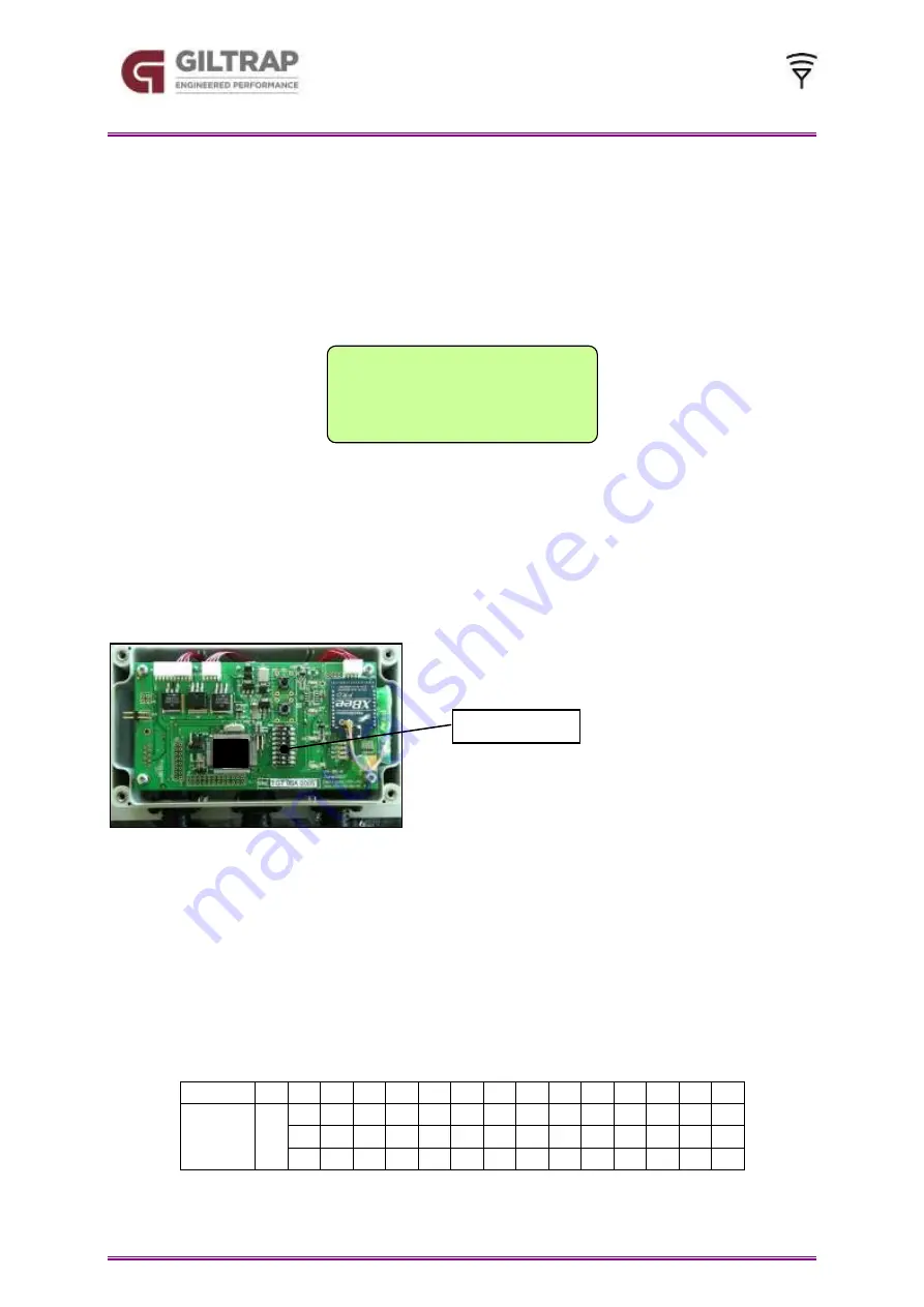
DIP switches
*** SETUP ***
RFID Number
1.00
Setting the RFID Number
The RFID Number setup screen is used to assign a wireless address to the Controller. This
feature is available to prevent interference between two systems when they are operated in
close proximity to each other.
To access the Remote Display RFID screen, re-power the display and press and hold the
MODE button until a setup screen appears.
The operator can press the UP button or the DOWN button to adjust this value. Press GO to
enter then STOP to escape. Re-power the Remote Display to access the new channel.
Controller Settings
After removing the Controller cover, a DIP switch with 8 white switches is visible.
The D.I.P. (dual inline plastic) switches which are labelled 1 to 8 are used to select
the RF channel ID.
The switch is considered to be ‘on’ when switched to the right hand side.
The channel ID of the Controller
MUST
match the software setting of the Remote
Display.
If the channel ID is changed in either the Remote Display or Controller then you must
re-power both devices for the new setting to take effect. To re-power the Controller,
unplug the POWER cable for 5 seconds.
The DIP switch settings are shown in the following table.
RFID #
0
1
2
3
4
5
6
7
8
9
10
11
12
13
14
Switch
On
Non
e
1
2
1
3
1
2
1
4
1
1
1
3
1
2
2
3
3
2
4
2
2
4
3
3
3
4
4
4


