


HD2010UC
- 57 -
V4.2
SERIAL INTERFACE
The instrument is provided with a versatile serial interface with double protocol: RS232C and
USB. The interface settings depend on the item “MENU >> General >> Input/Output >> Serial
Disp.”:
•
PRINTER: connection with RS232 interface of the portable serial printer.
•
MODEM: connection with RS232 interface to a modem.
•
RS232: connection with RS232 interface to a PC equipped with COM type physical port.
•
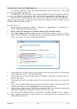
USB: connection with USB interface to a PC where the VCOM driver is installed.
The RS232 setting allows to connect the sound level meter to a COM type physical port of a
PC. This connection does not need any particular program to work as it is allowed by the common
architecture of PC equipped with RS232 (COM) port. The maximum speed of data transfer is up to
115200 baud.
In the last few years, in order to meet the needs of the new audio and video peripherals, the
USB standard has been used for information serial transfer. Recently many PC manufacturers do
not offer the COM type ports any longer, which are usually replaced by the USB type ports. There
is a 4 wire connection, two wires for information transfer, other two wires for the power supply. As
far as the data transfer is concerned, the main differences with respect to the RS232 interface RS232
are:
•
The transfer occurs in simplex mode, i.e. it’s impossible to carry out simultaneously a
transfer in both the directions
•
The data are transferred as package size
•
The transfer time is defined by only one of the two units (the master)
•
The transfer speed is fix at 1.5Mbit/s, 12Mbit/s or 480Mbit/s according to the USB stand-
ard and the kind of connected device.
The two devices connected through the USB interface are identified as master and slave. The
master supplies power to the slave and decide the sense and the transfer time scheduling.
The USB interface of sound level meter is a sort of slave and then it has to be connected to a
USB master able to supply with the necessary power and to manage the communication.
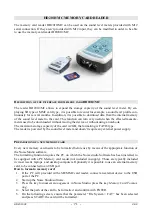
On the HD2010UC standard kit it is included a serial connection cable; the user can choose
between code HD2110RS for PC with COM ports or code HD2110USB for PC with USB ports.
The
HD2110/RS
cable is a
null-modem
cable with 9-way sub D female connector. The
HD2110/USB cable is fitted with an USB connector type A. On request, the connection cable for
modem or printer (DCE) with a 25-way sub D male connector (code
HD2110/CSM
) or with a 9-
way sub D male connector (code
HD2110/CSP
) can be supplied.
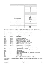
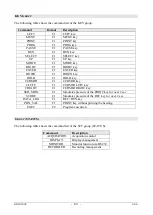
When the item “MENU >> Instrument >> Input/Output >> Serial Device” is set on “PRINTER”,
“MODEM” or “RS232”, the following signals are connected to the 8 pin male connector type M12
available on the instrument:
Pin
Direction Signal
Description
1
Input
CTS
Clear to send
2
Output
DTE
DTE ready
3
Input
DCE - CD
DCE ready – Carrier detect
4
Output
VDD
Power supply 3.3V
5
Input
RD
Receiving data channel
6
Output
RTS
Request to send
7
Output
TD
Transmitting data channel
8
-
GND
Reference ground
Summary of Contents for DeltaOHM HD2010UC
Page 2: ...HD2010UC 2 V4 2 ...
Page 129: ...HD2010UC 129 V4 2 NOTES ...
Page 130: ...HD2010UC 130 V4 2 NOTES ...
Page 131: ......


