


HD2010UC
- 58 -
V4.2
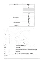
The following signals are connected to the 9 pin sub D male connector of the HD2110/RS cable:
Pin
Direction
Signal
Description
1
DCE >> HD2010UC DCE - CD
DCE ready – Carrier detect
2
DCE >> HD2010UC RD
Receiving data channel
3
HD2010UC >> DCE TD
Transmitting data channel
4
HD2010UC >> DCE DTE
DTE ready
5
-
GND
Reference ground
7
HD2010UC >> DCE RTS
Request to send
8
DCE >> HD2010UC CTS
Clear to send
9
HD2010UC >> DCE VDD
Power supply 3.3V
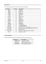
When the item “MENU >> General >> Input/Output >> Serial Device” is set on “USB”, the follow-
ing signals are connected to the 8 pin male connector type M12 available on the instrument:
Pin
Direction Signal
Description
2
I/O
DP
Datum +
4
I/O
DM
Datum -
6
Input
VBUS
Power supply 5V
8
-
GND
Reference ground
While the sound level meter is connected to an active terminal
(DCE active)
via the RS232 in-
terface, the auto power off is disabled and the instrument cannot be switched off
. If the instru-
ment is off, the connection to an active terminal (DCE active) will turn it on.
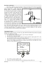
Standard parameters of the instrument serial transmission are:
•
Baud rate
baud 38400
•
Parity
None
•
N. bit
8
•
Stop bit
1
•
Protocol
Hardware.
Data transmission speed can be changed through the "
Baud rate
" parameter inside the menu -
(MENU >> Instrument >> Input/Output >> Baud Rate – see page 37). The available baud rates are:
230400, 115200, 57600, 38400, 19200, 9600, 4800, 2400, 1200, 600, 300. The other transmission
parameters are fixed.
The 2010UC is provided with a complete set of commands to be sent via the serial port of a PC.
Summary of Contents for DeltaOHM HD2010UC
Page 2: ...HD2010UC 2 V4 2 ...
Page 129: ...HD2010UC 129 V4 2 NOTES ...
Page 130: ...HD2010UC 130 V4 2 NOTES ...
Page 131: ......


