P74x/EN MT/Ma7
Maintenance
(MT) 11-
18
MiCOM P741, P742, P743
MT
1.3.2.8 Replacement of the Comms board
Before replacing a faulty Comms board (Communication board between central and
peripheral units), disconnect fibre optic cable connections at the rear of the relay.
The board is secured in the case by two screws accessible from the rear of the relay, one at
the top and another at the bottom, as shown in Figure 15. Remove these screws carefully as
they are not captive in the rear panel of the relay.
Using the small metal tab on the left hand side of the input module rotate handle used for
extraction until it is in a horizontal orientation. This is necessary so that the two PCB
connectors on the underside of the Comms board PCB do not catch the handle as the PCB
is extracted.
Gently pull the faulty Comms board PCB forward and out of the case.
P3764ENa
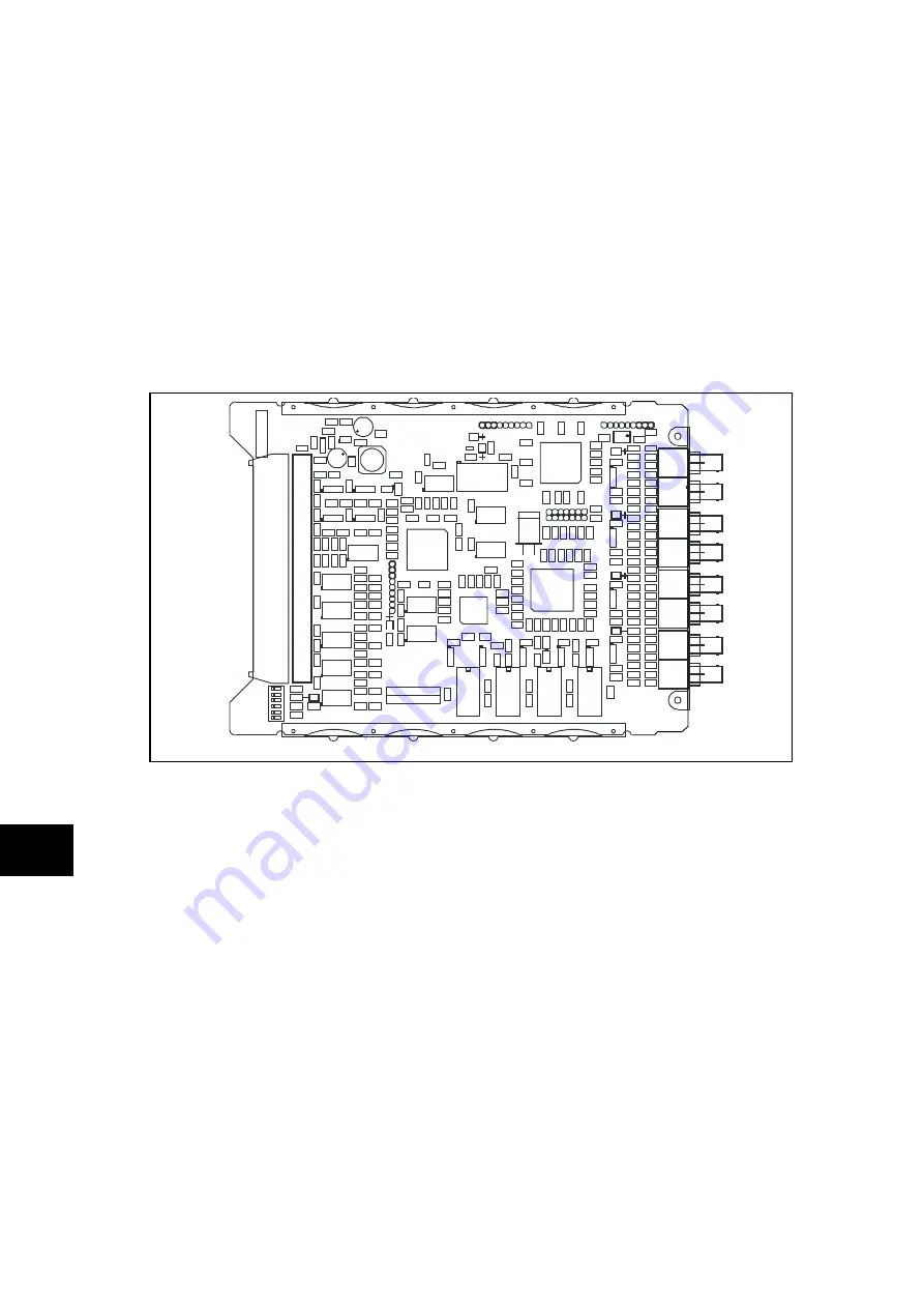
FIGURE 15: TYPICAL COMMS BOARD
To help identify that the correct board has been removed, Figure 14 illustrates the layout of
the Comms board with dual fibre optic communications channels fitted. The Comms board
boards with a single communications channel (used in relays for two ended feeders where
dual redundant communications channels are not required) use the same PCB layout but
have fewer components fitted.
The replacement PCB should be carefully slid into the appropriate slot, ensuring that it is
pushed fully back and the board securing screws are re-fitted.
Refit the fibre optic cable connections, ensuring that they are in the correct locations.
Refit the front panel using the reverse procedure to that given before. After refitting and
closing the access covers on size 60TE/80TE cases, press at the location of the
hinge-assistance T-pieces so that they click back into the front panel moulding.
Once the relay has been reassembled after repair, it should be recommissioned in
accordance with the instructions in sections 1 to 8 inclusive of the commissioning and
maintenance section P74x/EN CM.
Summary of Contents for P741
Page 2: ......
Page 4: ......
Page 6: ...P74x EN IT Na7 Introduction MiCOM P741 P742 P743 ...
Page 8: ...P74x EN IT Na7 Introduction IT 1 2 MiCOM P741 P742 P743 IT ...
Page 18: ...P74x EN TD Na7 Technical Data MiCOM P741 P742 P743 ...
Page 30: ...P74x EN TD Na7 Technical Data TD 2 14 MiCOM P741 P742 P743 TD ...
Page 32: ...P74x EN GS Na7 Getting Started MiCOM P741 P742 P743 ...
Page 70: ...P74x EN ST Na7 Getting Started MiCOM P741 P742 P743 ...
Page 72: ...P74x EN ST Na7 Settings ST 4 2 MiCOM P741 P742 P743 ST ...
Page 116: ...P74x EN OP Na7 Operation MiCOM P741 P742 P743 ...
Page 120: ...P74x EN OP Na7 Operation OP 5 4 MiCOM P741 P742 P743 OP ...
Page 136: ...P74x EN OP Na7 Operation OP 5 20 MiCOM P741 P742 P743 OP FIGURE 8 CB FAIL LOGIC ...
Page 166: ...P74x EN AP Na7 Application Notes MiCOM P741 P742 P743 ...
Page 234: ...P74x EN PL Na7 Programmable Logic MiCOM P741 P742 P743 ...
Page 290: ...P74x EN PL Na7 Programmable Logic PL 7 56 MiCOM P741 P742 P743 PL ...
Page 291: ...Programmable Logic P74x EN PL Na7 MiCOM P741 P742 P743 PL 7 57 PL ...
Page 292: ...P74x EN PL Na7 Programmable Logic PL 7 58 MiCOM P741 P742 P743 PL ...
Page 294: ...P74x EN PL Na7 Programmable Logic PL 7 60 MiCOM P741 P742 P743 PL ...
Page 295: ...Programmable Logic P74x EN PL Na7 MiCOM P741 P742 P743 PL 7 61 PL ...
Page 296: ...P74x EN PL Na7 Programmable Logic PL 7 62 MiCOM P741 P742 P743 PL ...
Page 298: ...P74x EN PL Na7 Programmable Logic PL 7 64 MiCOM P741 P742 P743 PL ...
Page 299: ...Programmable Logic P74x EN PL Na7 MiCOM P741 P742 P743 PL 7 65 PL ...
Page 300: ...P74x EN PL Na7 Programmable Logic PL 7 66 MiCOM P741 P742 P743 PL ...
Page 302: ...P74x EN MR Na7 Measurements and Recording MiCOM P741 P742 P743 ...
Page 324: ...P74x EN FD Na7 Firmware Design MiCOM P741 P742 P743 ...
Page 344: ...P74x EN FD Na7 Firmware Design FD 9 20 MiCOM P741 P742 P743 FD FIGURE 10 P74x SYSTEM OVERVIEW ...
Page 351: ...Firmware Design P74x EN FD Na7 MiCOM P741 P742 P743 FD 9 27 FD ...
Page 353: ...P74x EN CM Na7 Commissioning MiCOM P741 P742 P743 ...
Page 429: ...P74x EN MT Na7 Maintenance MiCOM P741 P742 P743 ...
Page 431: ...P74x EN MT Ma7 Maintenance MT 11 2 MiCOM P741 P742 P743 MT ...
Page 451: ...P74x EN TS Na7 Troubleshooting MiCOM P741 P742 P743 ...
Page 453: ...P74x EN TS Na7 Troubleshooting TS 12 2 MiCOM P741 P742 P743 TS ...
Page 475: ...P74x EN SC Na7 SCADA Communications MiCOM P741 P742 P743 ...
Page 499: ...P74x EN SC Na7 SCADA Communications SC 13 24 MiCOM P741 P742 P743 SC ...
Page 501: ...P74x EN SG Na7 Symbols and Glossary MiCOM P741 P742 P743 ...
Page 511: ...P74x EN SG Na7 Symbols and Glossary SG 14 10 MiCOM P741 P742 P743 SG Logic Gates ...
Page 513: ...P74x EN IN Na7 Installation MiCOM P741 P742 P743 ...
Page 515: ...P74x EN IN Na7 Installation IN 15 2 MiCOM P741 P742 P743 IN ...
Page 528: ...Installation P74x EN IN Na7 MiCOM P741 P742 P743 IN 15 15 IN FIGURE 6 P742 40TE REAR VIEW ...
Page 533: ...P74x EN VH Na7 Firmware and Service Manual Version History MiCOM P741 P742 P743 ...
Page 542: ...APPENDIX A WIRING DIAGRAMS ...
Page 543: ...Appendix A Wiring Diagrams P74x P74x EN M Na7 ...
Page 559: ......