


CHAPTER 5: SETPOINTS
S2 PROTECTION
MM3 MOTOR MANAGER 3 – INSTRUCTION MANUAL
5–17
•
GROUND FAULT TRIP LEVEL
: Some leakage current will always flow between the three
phases and ground due to capacitance, insulation, resistance, etc. On resistance
limited ground systems, the value selected must be below the maximum resistance
limited current that can flow or a trip will never occur. If no optimum value is known,
monitor actual leakage current then enter a current somewhat above this value.
Ground Fault Trips at a later time would indicate a deterioration in the system and
insulation integrity should be verified. Persistent, high values of leakage current pose
a threat to personnel and equipment and should not be left unchecked. If the
GROUND
FAULT CT INPUT
is set to “RESIDUAL”, the level is calculated as a percentage of full load
current; if the
GROUND FAULT CT INPUT
is set to “50:0.025 CBCT”, the level is calculated
in amps. Settings less than 1 A are not recommended.
•
GROUND TRIP DELAY ON RUN
: This delay is used when the motor is in a RUNNING
condition. If the ground current is equal to or above the
GROUND PRIMARY TRIP PICKUP
setpoint value and remains this way for the time delay programmed in this setpoint
while the motor is running, the assigned relay(s) will activate and the “CAUSE OF TRIP:
GROUND FAULT” message will be displayed. Refer to
details on how the MM3 Motor Manager 3 detects a start condition.
When the phase current increases from 0 A, the
GROUND TRIP DELAY ON START
setpoint described below is used until the
MM3 Motor Manager 3
determines whether
the motor is running or starting.
•
GROUND TRIP DELAY ON START
: This delay is used when the motor is in a starting
condition. If the ground current is equal to or above the
GROUND PRIMARY TRIP PICKUP
setpoint value and remains this way for the time delay programmed in this setpoint
while the motor is starting, the assigned relay(s) will activate and the “CAUSE OF TRIP:
GROUND FAULT” message will be displayed. Refer to
details on how the MM3 Motor Manager 3 detects a start condition.
When the phase current increases from 0 A, this delay is used until the
MM3 Motor
Manager 3
determines whether the motor is running or starting.
5.3.3
Motor
Protection:
Options
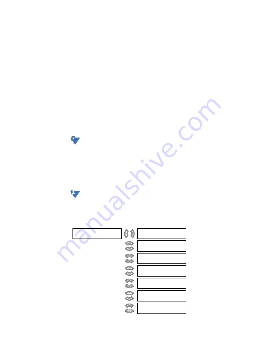
PATH: S2 PROTECTION
ÖØ
MOTOR PROTECTION OPTIONS
NOTE
NOTE
] MOTOR PROTECTION
] OPTIONS
MINIMIZE RESET TIME:
ENABLE
Range: Enable, Disable
STOPPED MOTOR COOL
TIME: 30 MINUTES
Range: 5 to 1080 minutes in steps of 1
OVERLOAD TRIP RESET:
MANUAL
Range: Manual, Auto
RESET LOCKOUT USING
RESET KEY: ENABLE
Range: Enable, Disable
PHASE UNBALANCE
ALARM: ENABLE
Range: Enable, Disable
THERMAL CAPACITY
ALARM: OFF %
Range: 1 to 100% or OFF in steps of 1
OPEN CONTROL CIRCUIT
TRIP: DISABLE
Range: Enable, Disable
Summary of Contents for MM3
Page 8: ...vi MM3 MOTOR MANAGER 3 INSTRUCTION MANUAL TABLE OF CONTENTS ...
Page 18: ...1 10 MM3 MOTOR MANAGER 3 INSTRUCTION MANUAL TECHNICAL SPECIFICATIONS CHAPTER 1 INTRODUCTION ...
Page 80: ...4 18 MM3 MOTOR MANAGER 3 INSTRUCTION MANUAL CHASSIS MOUNT UNITS CHAPTER 4 SOFTWARE ...
Page 124: ...5 44 MM3 MOTOR MANAGER 3 INSTRUCTION MANUAL S7 TESTING CHAPTER 5 SETPOINTS ...
Page 198: ...8 54 MM3 MOTOR MANAGER 3 INSTRUCTION MANUAL MODBUS MEMORY MAP CHAPTER 8 COMMUNICATIONS ...
Page 220: ...10 14 MM3 MOTOR MANAGER 3 INSTRUCTION MANUAL GE MULTILIN WARRANTY CHAPTER 10 MISCELLANEOUS ...