© 2019 Baker Hughes, a GE company, LLC. All rights reserved.
88
|
BHGE
Relay Removal and Installation
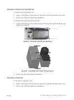
To remove the pneumatic relay:
1. Using a 3 mm hex key, remove the three screws from around the perimeter of the relay.
2. Lift the relay off the positioner.
Relay Installation
To install pneumatic relay:
1. Place the relay in the designated area on the positioner.
2. Using a 3 mm hex key, install the three screws around the perimeter of the relay.
Make sure that:
1. The five O-rings are seated in the base of the relay and are not damaged.
2. The three mounting screws are tight and torque to 15 in-lb (1.7 N-m).
Adjusting I/P Zero
The I/P Zero is calibrated at the factory prior to shipment. If there is a problem with I/P zero
please contact your representative.
Connecting Components to the Electronics Module
If it is necessary to remove and install any SVI FF component you may need to reconnect the
component to the SVI FF Electronics Module via the SVI FF Terminal Board. Refer to “Wiring
the SVI FF” on page 65 of this manual for instructions.
When you have completed maintenance on the pneumatic relay it
is necessary to reinstall the pneumatic cover. Refer to on
“Pneumatic Cover Installation” on page 87.
CAUTION
Summary of Contents for Baker Hughes Masoneilan SVI FF
Page 12: ...This page intentionally left blank ...
Page 72: ...This page intentionally left blank ...
Page 82: ...This page intentionally left blank ...
Page 94: ...This page intentionally left blank ...
Page 108: ...This page intentionally left blank ...
Page 198: ...This page intentionally left blank ...
Page 206: ...This page intentionally left blank ...
Page 224: ...This page intentionally left blank ...
Page 228: ...This page intentionally left blank ...
Page 230: ...This page intentionally left blank ...
Page 250: ...This page intentionally left blank ...
Page 262: ...This page intentionally left blank ...
Page 263: ......

