Modifications reserved
Page 87/99
OPM_SPE_XXX_10K_40K_8GB_V020.doc
Operating Manual
SitePro 10-15-20-30-40 kVA / S8
9.1.3 Output signals on voltage-free contacts
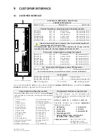
The interface board provides
6 voltage free relay contacts
giving some UPS critical alarms and
operation mode.
These signals are available either on connector
J2
- (sub D, female 25 pin)
or terminal blocks
X1
.
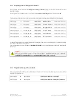
The meaning of the alarms on the free contacts in standard configuration (default) is the following:
X1 / 1, 2, 3
or
J2 / 1, 2, 3
(NO, C, NC)
Mains Failure
(def. Parameter RL=1)
X1 / 4, 5, 6
or
J2 / 4, 5, 6
(NO, C, NC)
Load on Inverter
(def. Parameter RL=3)
X1 / 7, 8, 9
or
J2 / 7, 8, 9
(NO, C, NC)
Stop Operations
(def. Parameter RL=5)
X1 / 12, 13, 14
or
J2 / 14, 15, 16
(NO, C, NC)
Load on Mains
(def. Parameter RL=2)
X1 / 15, 16, 17
or
J2 / 17, 18, 19
(NO, C, NC)
General Alarm
(def. Parameter RL=4)
X1 / 18, 19, 20
or
J2 / 20, 21, 22
(NO, C, NC)
Acoustic Alarm
(def. Parameter RL=6)
In case different alarms or operating status are required, they can be configured on the same terminals
via software from the
control panel
.
The configuration can be changed in
parameters mode
by a trained operator using the appropriate
password.
NOTE !
The programmable signals on
X1
and
J2
will be disabled with
Q1
open, with the
exception of the signals for
“16 - Manual Bypass Q2 ON”
and
“26 - EPO”
.
9.1.4 Programmable input free contacts
Some programmable UPS functions (indicated in
Section 9.1
), can be activated by closing an external
contact, if connected, on:
X1 / 10, 21
or
J2 / 10, 23
User Input 1 (default = Not used)
X1 / 11, 22
or
J2 / 11, 24
User Input 2 (default = Emergency GEN ON)

